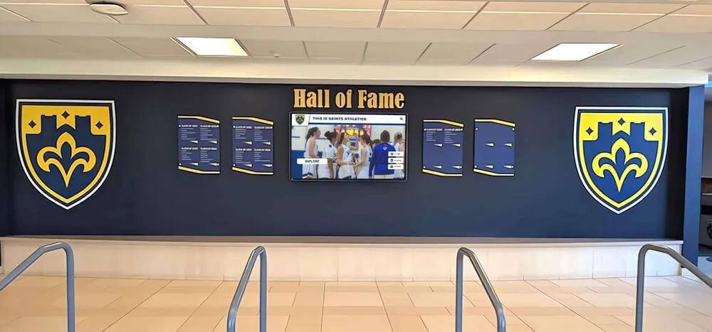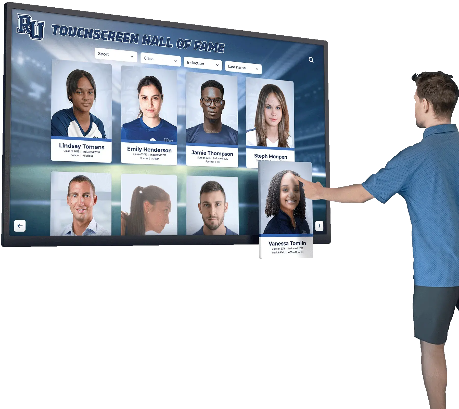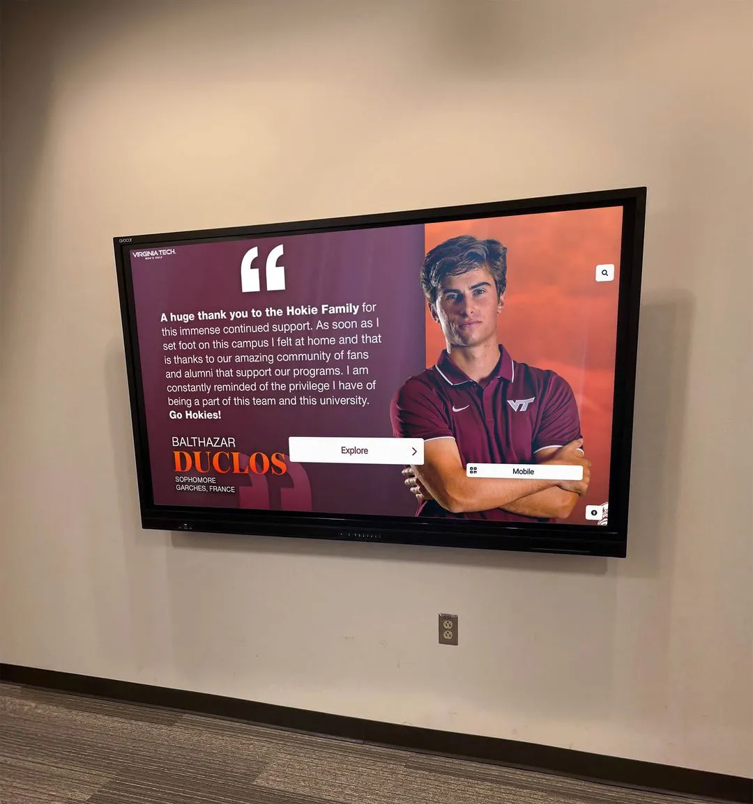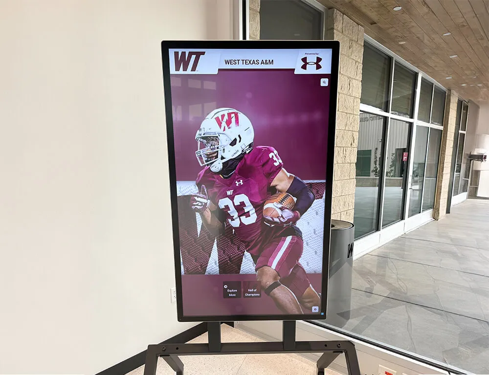


A recognition display cable strain relief inspection gives school facilities coordinators and IT teams a structured walk-through to confirm that every power cord, network cable, and AV connection on a touchscreen hall of fame or athletic recognition display is mechanically protected against the pulling, bending, and vibration that accumulate across a full school year. Strain relief—the hardware and routing practice that prevents cable conductors from bearing tension at their termination points—is required by the National Electrical Code (NFPA 70, Section 400.10) for power cords and is a best practice enforced by structured cabling standards (TIA-568) for data connections. When it fails, the consequences range from intermittent display dropouts and data errors to exposed conductors that present a safety hazard in a busy school corridor.
Recognition displays occupy some of the highest-traffic areas in a school building: main lobbies, athletic hallways, gymnasium entrances, and trophy case alcoves where students, parents, visiting teams, and alumni pass daily. Those locations expose cables to accidental snagging by equipment carts, contact from cleaning crews, and stress from repeated maintenance access. This guide gives facilities managers, IT coordinators, and athletic directors a clear inspection workflow they can run at installation, at the start of each school year, and after any display service call.
A complete recognition display cable strain relief inspection covers six steps: scheduling and preparation, power cable and plug inspection, network patch cable inspection, AV and USB cable inspection, cable management hardware inspection, and documentation with remediation follow-up. Each step has clear pass/fail criteria and an assigned owner so nothing falls through the gap between IT and facilities.

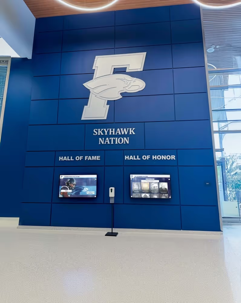
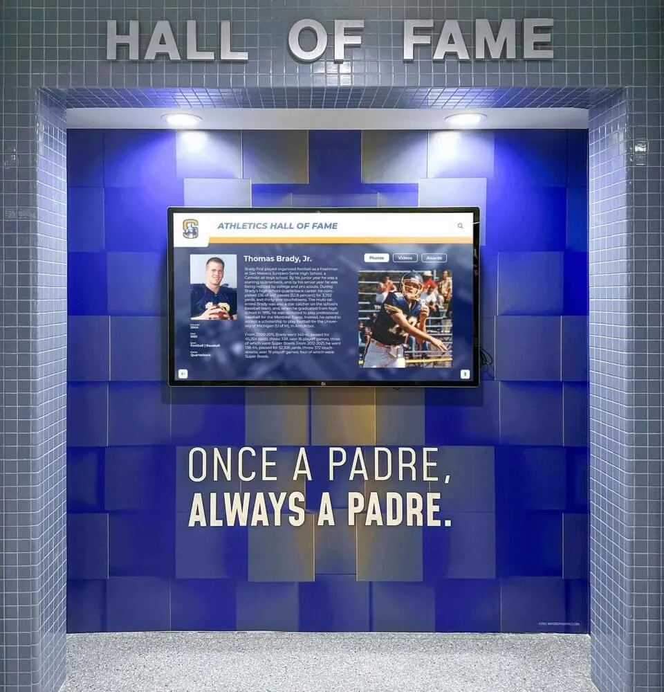
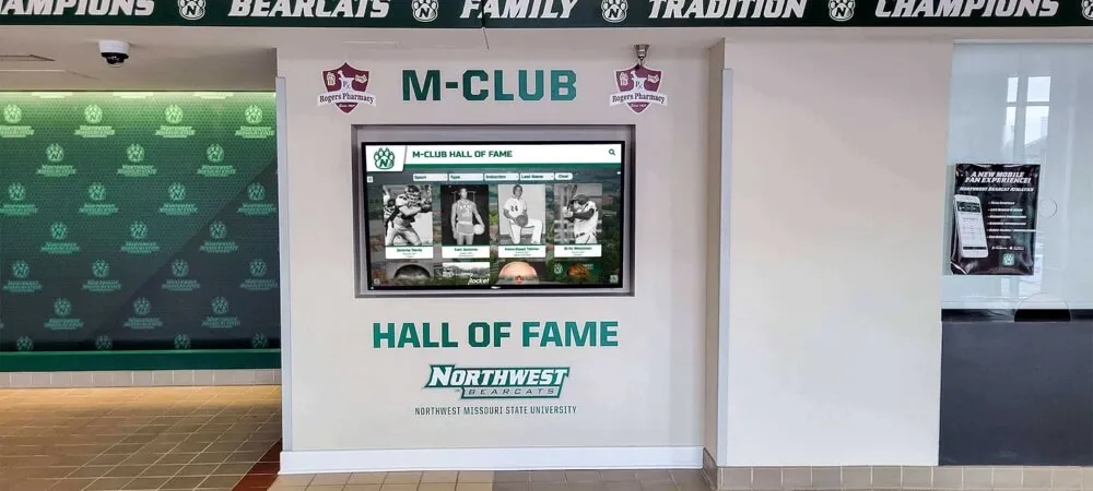
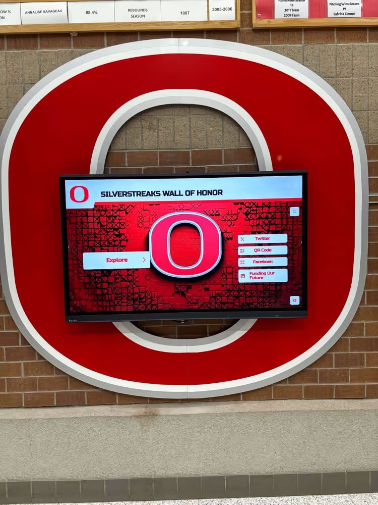
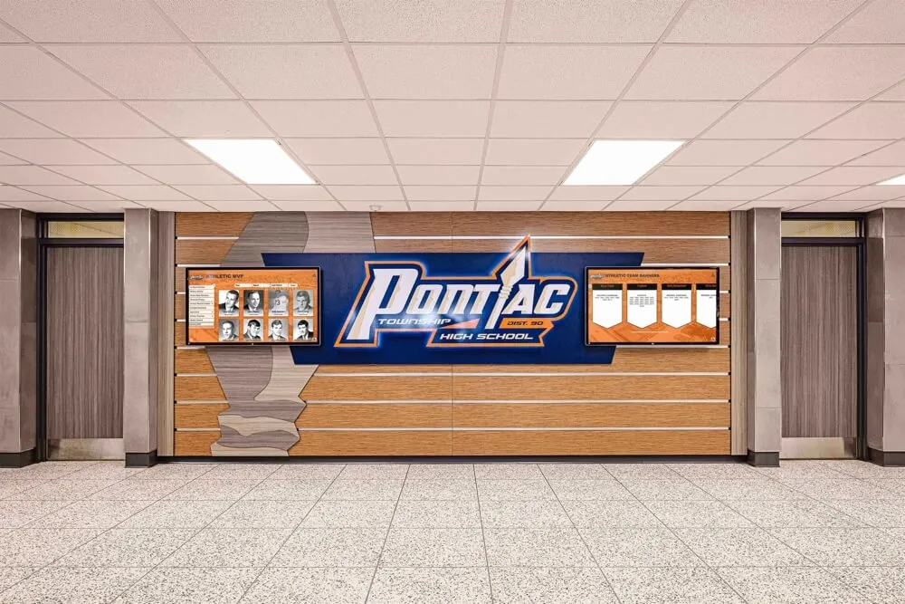
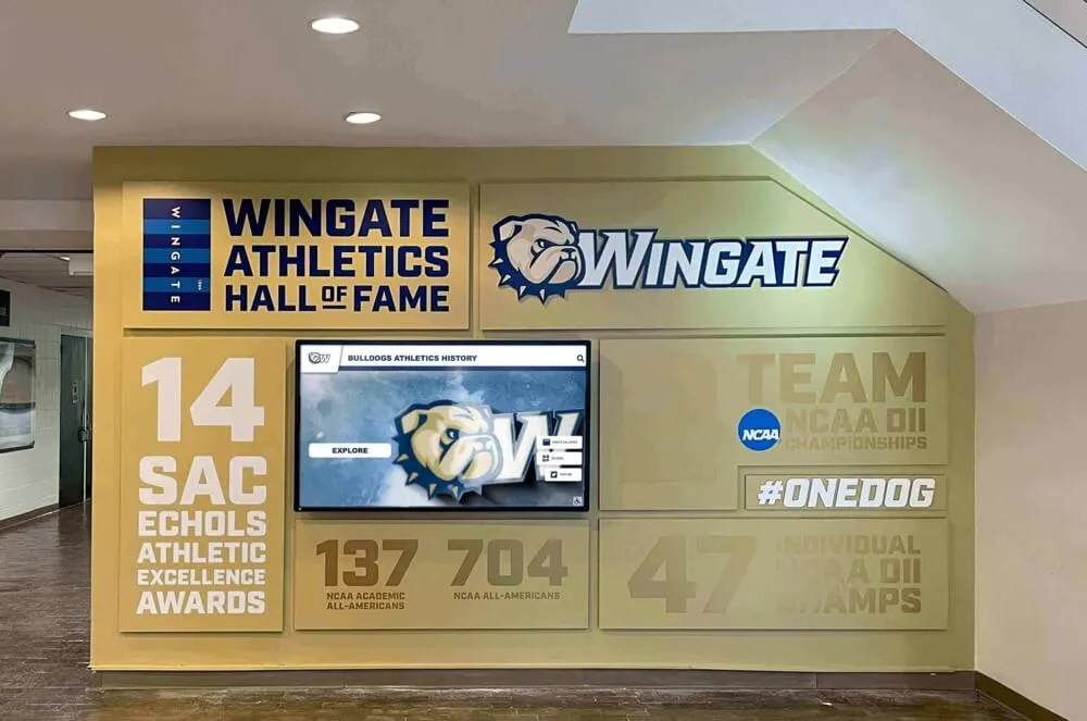
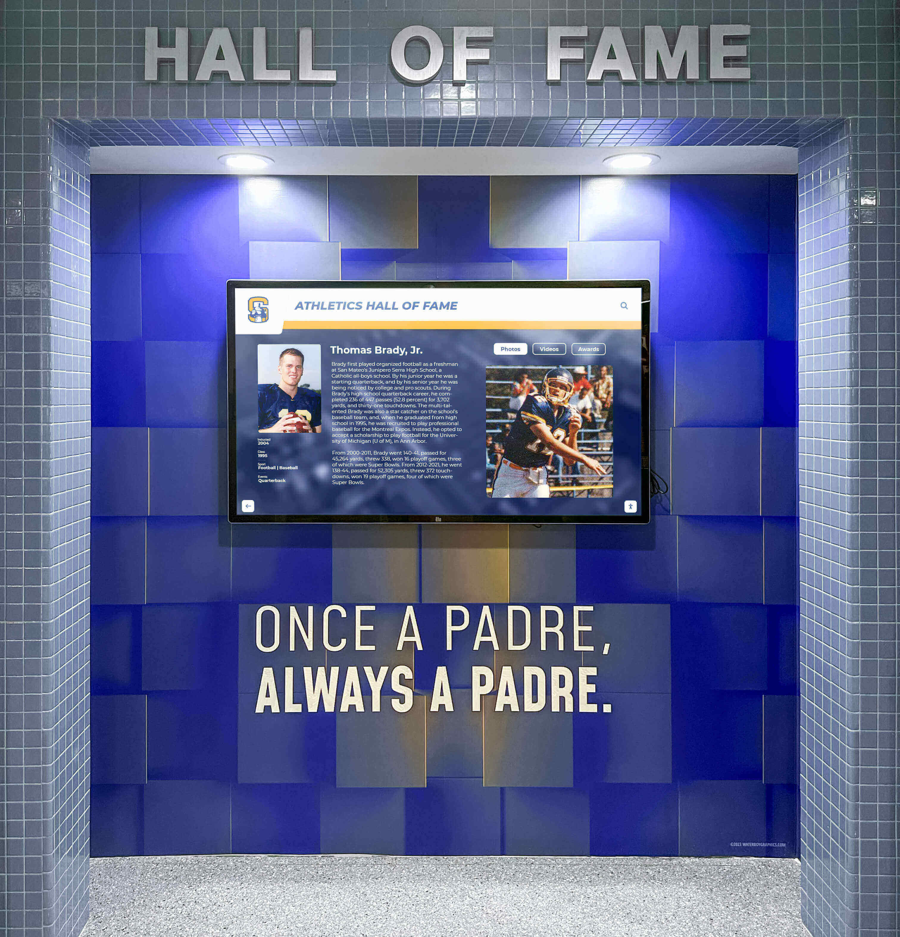
Recognition displays in high-traffic school hallways are exposed to incidental cable stress from carts, cleaning equipment, and daily maintenance access — a scheduled strain relief inspection catches damage before it disrupts the display or creates a safety hazard.
Why Cable Strain Relief Matters for Recognition Displays Specifically
Cable strain relief is an electrical code requirement and a cabling standard, but its practical importance on school recognition displays is shaped by factors specific to these installations.
Continuous operation increases cumulative stress. Most school computers and AV equipment are powered down at the end of the day. Recognition displays typically run on a scheduled or 24/7 cycle, which means power and data cables never experience the relaxation that comes with being unplugged. Thermal expansion and contraction across daily temperature cycles flex cable terminations repeatedly over months.
Lobby and hallway locations attract incidental contact. A recognition display installed in the main lobby or at a gym entrance sits in a traffic corridor. Equipment carts, cleaning machines, and groups of students brushing past can generate lateral force on power cords and patch cables, especially when cables run along the floor between the display enclosure and the nearest outlet or data port.
Content that represents institutional history cannot afford unplanned outages. A touchscreen athletic hall of fame holds decades of inductee records, championship documentation, and award histories that families and alumni expect to find visible at any time—during morning arrival, during homecoming week, during halftime of a championship game. A cable failure that takes a display offline at the wrong moment is a recognition failure. Schools that host alumni networking events and reunion gatherings around their recognition programs face amplified impact when a display goes dark during a high-attendance evening.
Maintenance access creates repeated strain cycles. Any time a technician services the display—replacing a media player, updating cabling, or cleaning the enclosure—cables are shifted, disconnected, and reconnected. Without proper strain relief hardware, each service cycle introduces a new opportunity for conductor damage at termination points.
Regulatory Baseline for Cable Strain Relief on Display Installations
Power Cords (NFPA 70)
NFPA 70 Section 400.10 requires that flexible cords be connected to devices and fittings so that tension is not transmitted to joints or terminals. Cord clamps, strain-relief bushings, or equivalent fittings at the point where a cord enters an enclosure satisfy this requirement. Inspect for compliant fittings at every power entry point on the display enclosure and media player housing.
Data Cables (TIA-568)
TIA-568 structured cabling standards specify minimum bend radius and pulling tension limits for network patch cables. Patch cords bent tighter than their rated minimum bend radius — typically four times the cable's outer diameter for Category 6 — suffer performance degradation and eventual conductor damage. Inspect cable routing at wall plates, patch panels, and the display enclosure's network port for tight bends and kinks.
Step 1: Schedule and Prepare the Inspection
A strain relief inspection takes thirty to sixty minutes per display location when well organized. Scheduling it correctly ensures the inspection is thorough and does not disrupt school programming.
Schedule around the recognition program calendar. Identify inspection windows that fall outside major events — induction ceremonies, homecoming weekends, athletic banquets, and alumni programming nights. Schools running active alumni of the month recognition programs announce honoree reveals through their recognition displays; coordinate with the program coordinator before scheduling any inspection that may require taking the display offline briefly.
Assemble the inspection team and tools. The inspection works best when the IT coordinator (responsible for the display’s network and computing components) and a qualified facilities staff member (responsible for the electrical and physical installation) conduct it together. Bring a flashlight or inspection light, a camera or phone for documentation, a copy of the display’s original installation diagram, and the vendor’s hardware specifications sheet listing cable types and bend radius requirements.
Obtain the installation documentation. Review the original installation records: mounting method, cable routing paths, conduit runs, and whether cables were run in-wall or surface-mounted. If installation records are unavailable, document the current installation during this inspection to create the baseline record for future inspections.
Notify stakeholders. Even a non-disruptive inspection warrants a brief notification to the athletic director and front office. If the inspection may require briefly powering down the display, treat it as a planned maintenance window and communicate the expected outage window in advance.
Confirm your right to work. If the display is installed in a leased or co-occupied space — a shared athletic facility, a conference room used by a booster organization — confirm authorization before moving or inspecting cabling that runs through the building’s walls or conduit systems.
Step 2: Inspect Power Cables and Strain Relief Fittings
Power cable failures carry the highest safety risk. Inspect every power connection systematically from the outlet to the display.

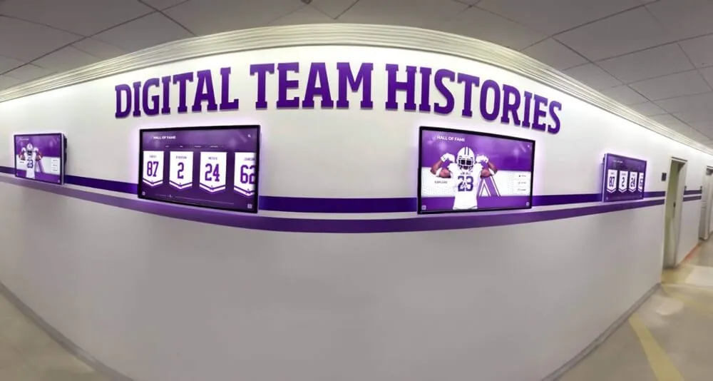
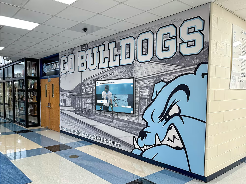
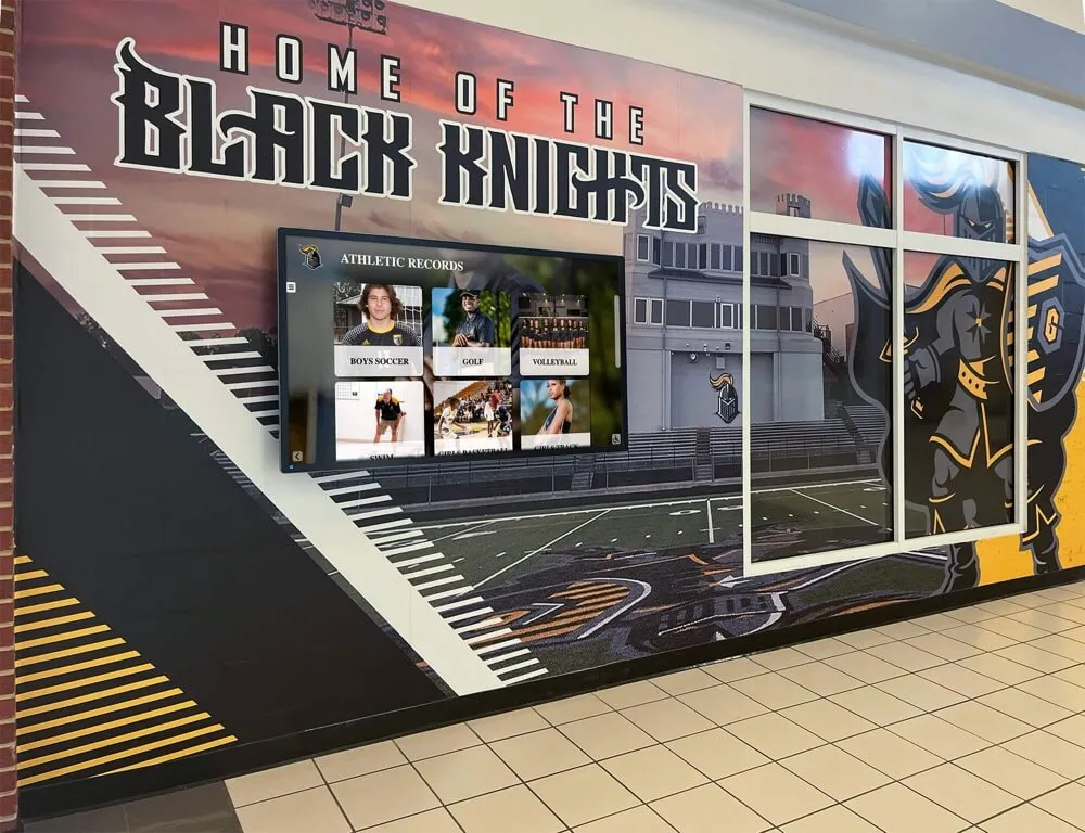
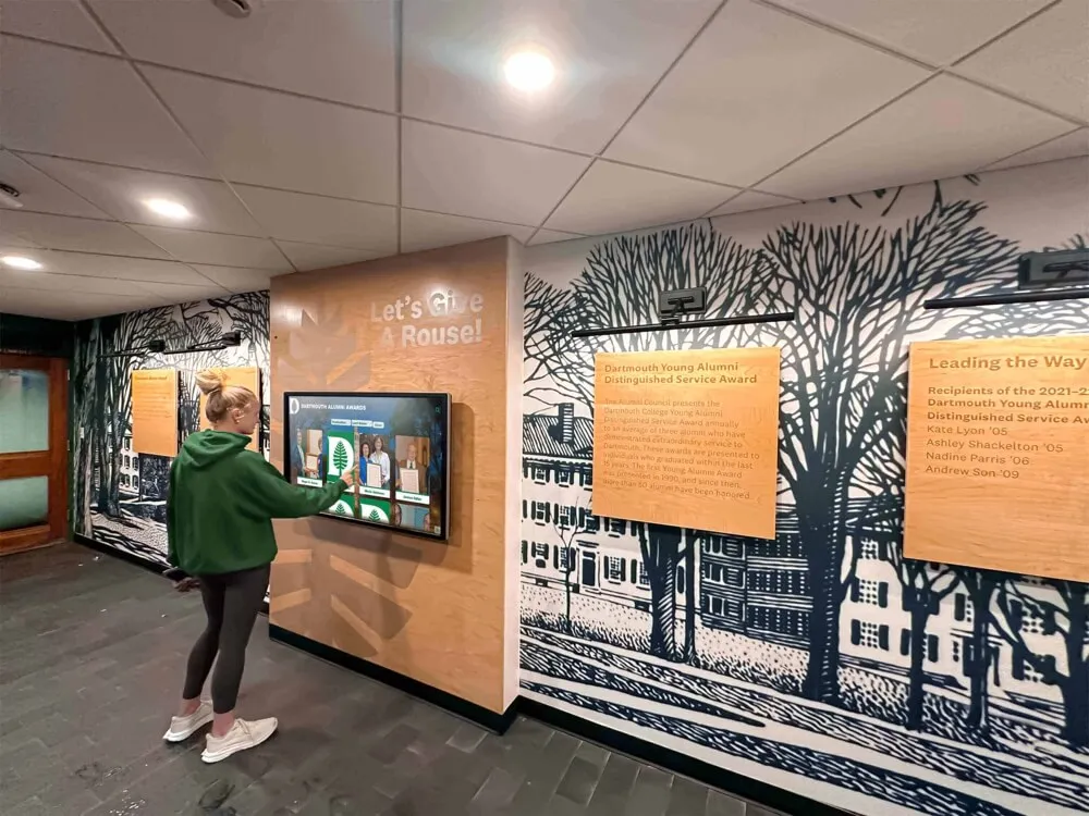
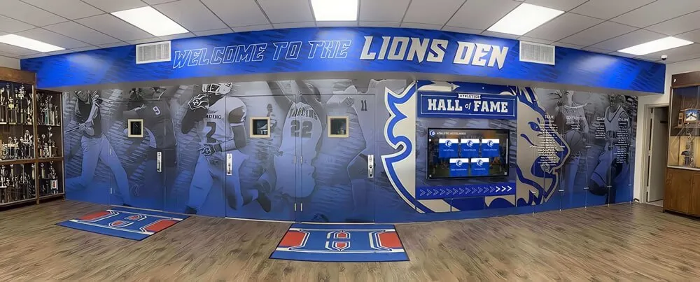
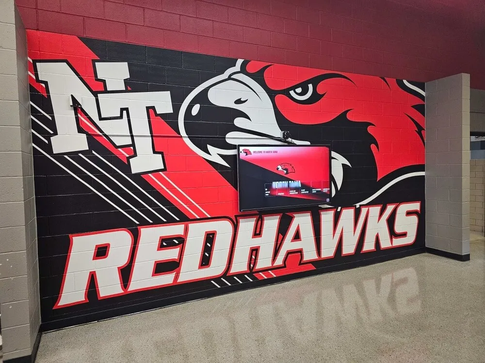
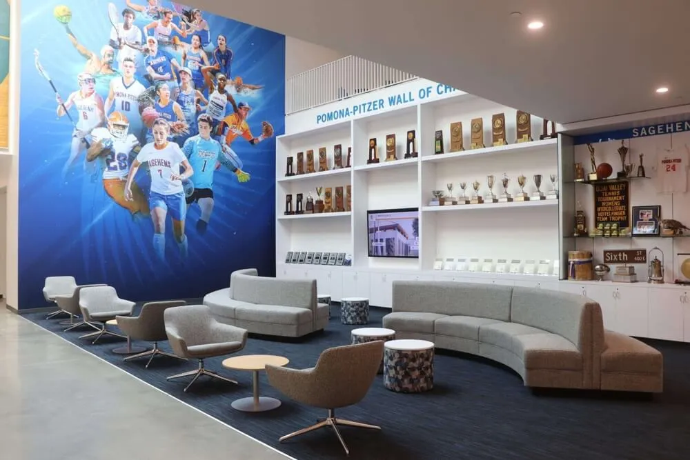
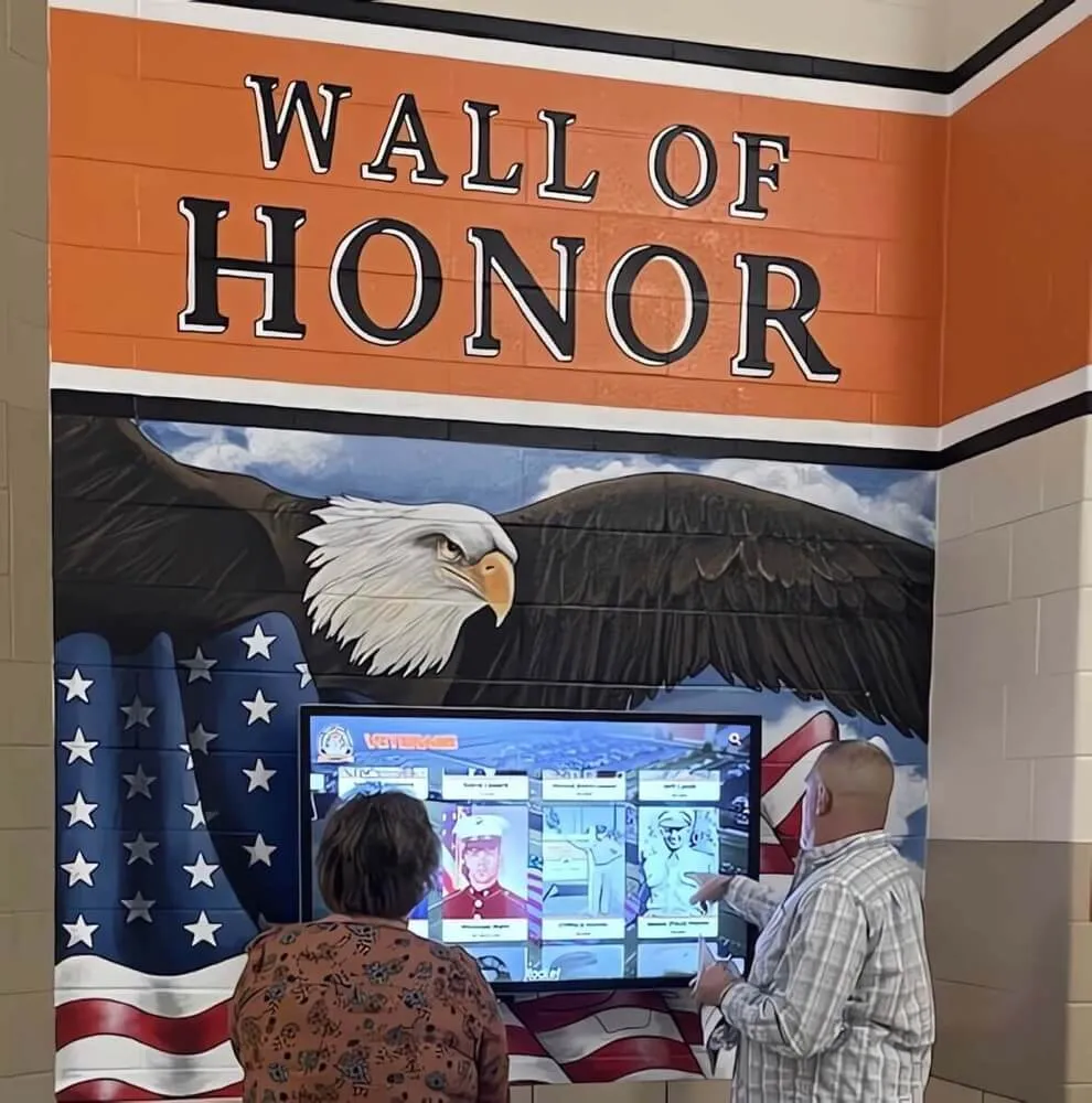
Displays installed alongside murals and recognition walls in school hallways often have cables routed behind wall panels or along baseboards — inspect the full length of each cable run, not just the visible termination points.
Inspect the wall outlet and plug. Confirm the display’s power cord plug is fully seated in the outlet with no gap at the blade contact. Check for discoloration, scorch marks, or deformation around the outlet face or plug blades — any of these indicates heat buildup from a poor connection and requires immediate electrician review before the inspection proceeds further.
Check the power cord for physical damage along its full length. Trace the cord from the outlet to the display enclosure. Look for kinking (a sharp bend that stays set after the cord is straightened), cracking of the outer jacket, flattening from compression under furniture or cord covers, and any point where the jacket has been cut or abraded. A cord with visible jacket damage must be replaced — do not tape over damage to power cords.
Verify the cord clamp or strain-relief bushing at the enclosure entry point. At the point where the power cord enters the display enclosure or media player housing, there should be a cord clamp, grommet, or strain-relief bushing that grips the cord’s outer jacket. Pull gently on the cord at this point — it should not be possible to pull the cord through the fitting or to generate tension at the internal terminal connection. If the cord slides freely through the entry hole, a strain-relief fitting is missing and must be installed.
Confirm the cord is not stretched taut between the outlet and the enclosure. A cord that is pulled straight with no slack is bearing tension across its full length. Tension at terminations is what NFPA 70 Section 400.10 prohibits. Ensure there is adequate slack — at least a gentle loop or S-bend — so incidental pulling on the cord at the outlet end does not transmit force to the terminal inside the display.
Inspect the IEC connector at the display (if applicable). Many display enclosures use an IEC C13/C14 power connector between the cord and the display chassis. Confirm the connector is fully seated, the retaining clip (if present) is engaged, and the connector housing shows no cracks or discoloration.
| Power Cable Inspection Point | Pass Condition | Fail Condition — Required Action |
|---|---|---|
| Wall outlet and plug | Fully seated, no discoloration or heat marks | Remove from service; electrician review before return to use |
| Cord jacket (full length) | No kinking, cracking, flattening, or abrasion | Replace cord; do not tape over jacket damage |
| Strain-relief fitting at enclosure entry | Cord gripped firmly; cannot be pulled through | Install compliant cord clamp or bushing immediately |
| Cord slack | Gentle loop or S-bend between outlet and enclosure | Reroute cord or use a longer replacement cord to restore slack |
| IEC connector (if applicable) | Fully seated, retaining clip engaged, no cracks | Reseat or replace connector; replace cracked housing |
Step 3: Inspect Network Patch Cables
Network connectivity is what keeps recognition content current — inductee records, photo updates, and championship documentation arrive via the cloud sync connection. Network cable strain relief failures cause intermittent sync failures that may not be obvious until content is visibly outdated.
Trace the network patch cable from the wall plate to the display. Network cables in school hallway installations are often routed behind wall-mounted displays, through cable channels, or along baseboard runs. Trace the full cable path and look for points where the cable bends sharply around corners, is pinched under the display mount, or passes through a hole without a protective grommet.
Verify the bend radius at all routing bends. Category 5e and Category 6 patch cables have a minimum bend radius typically specified as four times the cable outer diameter. A tightly kinked cable at a corner or around a conduit fitting has likely exceeded this limit. Straighten the routing using a larger radius bend, a corner bracket, or a cable management accessory designed to guide cables around corners without sharp bends.
Inspect the RJ-45 plugs at both ends. Pull gently — with less than 10 lbs of force — on each end of the network cable. The plug should not pull out of the jack. The boot behind the plug should be intact and not cracked. A plug that releases with minimal force, or a plug whose locking tab has broken, lacks the mechanical retention that prevents the cable from being accidentally disconnected when someone brushes past the display enclosure.
Check for kinking at the wall plate and at the display’s network port. The first six inches of cable from any connector is the highest-stress zone. At the wall plate, confirm the cable enters straight and has a natural curve rather than a tight 90-degree bend. At the display enclosure, confirm the cable does not exit the network port at a right angle that puts stress on the RJ-45 plug body.
Confirm the cable is routed away from electromagnetic interference sources. Power cables, fluorescent ballasts, and athletic facility lighting are common EMI sources in school hallways. Data cables should maintain separation from power cables per TIA-568 guidelines — a minimum of 2 inches from non-conduit power conductors in a typical parallel run, with more separation required if the power conductors are not in grounded metallic conduit.
Network Cable Inspection Checklist by Location
At the Wall Plate
Cable enters jack straight without bending the plug body. Boot is intact. Cable exits plate with a natural curve, not a right-angle bend. No kink within six inches of the plug. Wall plate is mounted flush with no gap allowing cable to be compressed between plate and wall.
Along the Routing Path
No sharp bends tighter than four times the cable's outer diameter. Cable is not pinched under display mount hardware, cable covers, or furniture. Cable runs are separated from power conductors by at least 2 inches for parallel runs. Cable does not contact sharp edges that could abrade the jacket over time.
At the Display Network Port
Plug is fully seated and locking tab engages. Boot is intact. Cable exits the port with a natural bend, not a right angle. Cable is not under tension that would pull the plug away from the port during normal thermal expansion or incidental contact.
Step 4: Inspect AV and USB Cables
Recognition displays use HDMI, DisplayPort, or USB connections between the media player and the display panel, and may include USB extensions for touch sensor arrays. These cables are under frequent stress during service calls and are often overlooked in standard IT maintenance checklists.
Inspect the video cable (HDMI, DisplayPort, or proprietary) at both ends. Confirm the connector is fully seated in both the media player output and the display panel input. HDMI and DisplayPort connectors that are partially seated — often the result of being bumped during a service call — cause intermittent signal loss that presents as a flickering screen or a display that cycles through resolution modes. These symptoms are easily misdiagnosed as a software problem.
Check for locking mechanisms or cable retention accessories. Standard HDMI and DisplayPort connectors have no locking mechanism. Display installations that use active media players accessible from the front of the enclosure benefit from locking HDMI adapters or cable anchor brackets that prevent accidental disconnection. If the installation does not have cable retention on the video connection, note this as an improvement recommendation.
Inspect USB cables and extensions for the touch sensor. Many touchscreen recognition displays use a separate USB cable from the display panel to the media player to carry touch input data. These cables are often routed through tight bends inside the display enclosure. Inspect the full length of the USB cable for jacket damage, confirm both connectors are fully seated, and verify that the cable is not compressed between the display panel and the back of the enclosure when the display is mounted flush to the wall.
Verify that all AV cables are secured to prevent swing. A HDMI or DisplayPort cable that is long enough to form a loop inside the enclosure can swing when the display is accessed for service, introducing repeated bending stress at the connector body. Use hook-and-loop cable ties or cable anchors inside the enclosure to prevent free movement.

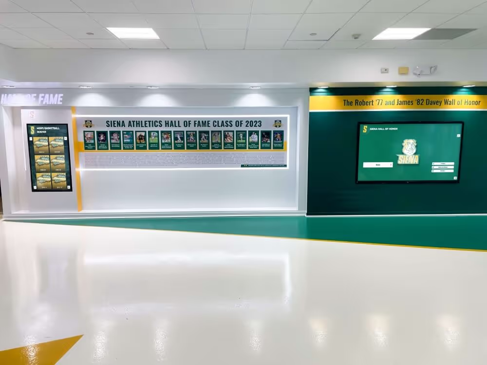
Multi-screen recognition installations in school hallways double the number of cable connections requiring inspection — each display's power, network, and AV connections need individual verification regardless of how closely the units are installed together.
Step 5: Inspect Cable Management Hardware
Strain relief hardware — clamps, grommets, bushings, cable ties, and conduit fittings — is what transforms a cable installation from a functional connection into a mechanically protected one. Inspect each hardware component for condition and continued effectiveness.
Inventory all strain-relief hardware on the installation. On the display enclosure, wall plate, and anywhere cables transit a panel or housing, identify every cord clamp, grommet, bushing, and cable anchor. Cross-reference against the installation documentation — any fitting present in the original installation but missing from the current configuration represents a gap in protection.
Check grommets for cracking or deformation. Rubber and plastic grommets at cable entry points age under UV exposure, heat, and repeated cable movement. A grommet that has cracked or deformed may no longer protect the cable jacket from abrasion at the panel edge. Replace any grommet that is no longer seating flat in its hole or that shows cracking.
Verify cord clamp tightness. Cord clamps should grip the cable outer jacket firmly without crushing it. A clamp that is too loose allows the cable to slide; a clamp that is too tight crushes the jacket and can damage conductors over time. Verify that clamps are set to the correct tightness for the cable diameter and that no clamp has loosened from vibration or thermal cycling.
Inspect cable ties for tightening and brittleness. Cable ties used to bundle or route cables in display enclosures become brittle over time, particularly in installations subject to temperature swings in uninsulated athletic facilities. A brittle cable tie that breaks under load can allow bundled cables to fall across circuit boards or heating elements inside the enclosure. Replace any cable tie that shows discoloration, cracking, or that breaks when flexed with minimal finger pressure. Use releasable cable ties in service-access areas to facilitate future maintenance.
Check conduit fittings at all conduit entry points. Where cables enter or exit conduit — a common installation method for routing power and data through walls in school facilities — the fitting at the conduit end must include a bushing that protects the cable jacket from the sharp edge of the conduit. Verify that all conduit fittings are secure and that protective bushings are in place and undamaged.
Assess cable tray and raceway condition. Cable trays, surface raceways, and J-hooks used to route cables to the display location should be inspected for sharp edges caused by impact damage or corrosion. A cable raceway with a crack or bent edge can abrade a cable jacket over months of operation. Replace damaged sections or use edge protection to eliminate sharp contact points.
| Hardware Component | Inspect For | Replacement Trigger |
|---|---|---|
| Cord clamps at enclosure entry | Grip strength, correct cable diameter match, no crushing | Cable slides when pulled; clamp is stripped or deformed |
| Grommets at panel holes | Cracking, deformation, seated flat in hole | Any cracking or grommet dislodged from hole |
| Cable ties in enclosure | Brittleness, discoloration, tightness | Any cracking, breaks under minimal flex, discolored from heat |
| Conduit bushings | Present at all conduit ends, undamaged | Missing bushing; cracked or missing protective lip |
| Cable raceway / tray | Sharp edges from impact damage or corrosion | Any visible sharp edge in contact with cable jacket |
Step 6: Document Findings and Follow Up on Remediation
An inspection that does not result in documentation provides no lasting protection. The inspection record is the evidence base for future inspections, vendor support calls, and facilities budget planning.
Photograph every finding before remediation. A photo of each identified issue — a kinked cable, a missing grommet, a cord with jacket damage — documents the condition at the time of inspection and supports the work order created to correct it. Label photos by display location and finding type.
Classify each finding by priority. Not all findings require the same response timeline. Use a three-tier classification:
- Immediate: Safety-critical findings (exposed conductors, heat damage at outlet, missing strain relief on power cord) require the display to be removed from service until corrected.
- Near-term: Functional-risk findings (missing boot on network connector, kinked patch cable, cracked grommet) require correction within two weeks and before any major recognition event.
- Scheduled: Improvement-only findings (no locking HDMI adapter, releasable cable ties not used in service areas) can be addressed at the next maintenance window.
Create work orders for each remediation action. Route immediate and near-term findings to the appropriate owner — electrician for power cord replacement, IT coordinator for patch cable replacement, facilities maintenance for conduit bushing replacement. Attach the inspection photo to each work order.
Verify remediation before closing the inspection record. After each work order is completed, conduct a brief verification walk-through to confirm the finding has been correctly addressed. A replaced cord with no new strain relief fitting is not a remediation — it is the same deficiency in a newer component.
Update the installation documentation. If the inspection reveals that the current installation differs from the original documentation — cables rerouted, hardware missing, new components added without documentation — update the installation record to reflect the current verified state.
Schools managing archives of athletic history alongside their display programs benefit from applying a comparable documentation discipline to their recognition content records. Resources like the athletic archive source reliability rubric and athletic archive scanning resolution guidelines illustrate how systematic documentation frameworks protect institutional records — the same discipline applied to installation documentation protects the hardware delivering those records to visitors.
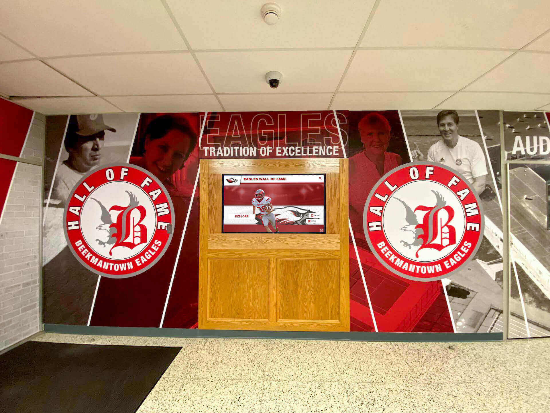
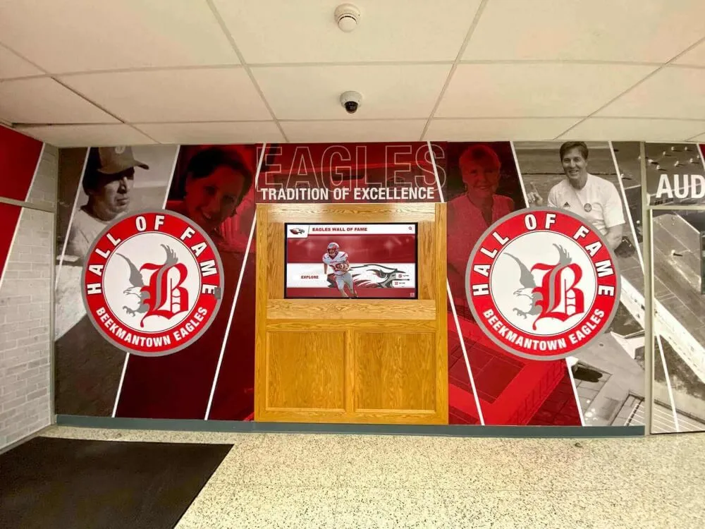
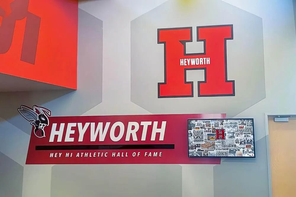
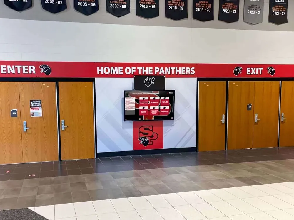
School lobbies that feature both murals and recognition displays often involve complex cable routing behind wall panels and through finished surfaces — inspection documentation that maps every cable path prevents guesswork during future service calls.
Recurring Inspection Schedule
A one-time inspection establishes the baseline. A recurring schedule maintains it through the events and seasons that matter most to the school community.
| Inspection Type | Frequency | Scope | Owner |
|---|---|---|---|
| Visual spot check | Monthly | Walk past each display; look for exposed cables, damaged cord at outlet, obvious physical contact damage | Facilities staff |
| Full strain relief inspection | Annually (August) | All 30 checklist items; full documentation update; photos of findings | IT coordinator + facilities |
| Post-service inspection | After every service call | Steps 6–19: power cord, strain relief, network cable, AV cable; confirm all connections re-seated correctly | IT coordinator |
| Pre-event confirmation | 48 hours before major events | Visual check of cord at outlet, network plug engagement, AV cable seating; confirm display operating normally | IT coordinator |
| Post-incident review | After any display outage or physical impact | Full inspection of affected display; check for cord damage or displaced connections caused by the event | IT coordinator + facilities |
The August annual inspection aligns with the school year startup, giving facilities and IT teams the full inspection period before homecoming, fall sports championships, and the year’s first induction ceremonies create blackout windows for maintenance. Schools planning to submit a booster club budget that includes display maintenance should complete the annual inspection before booster club investment policy discussions in September, so that any parts or service costs identified during inspection can be included in the planning cycle. A completed booster club meeting agenda that includes a brief IT facilities report gives booster leadership visibility into what the recognition infrastructure requires to remain reliable.
Connecting Strain Relief Inspection to Athletic Recognition Operations
Cable inspection is a technical discipline, but its importance is grounded in what the display delivers: the athletic history, award records, inductee profiles, and achievement archives that represent decades of school identity. A display that goes offline because of a cord failure during a championship night or a hall of fame induction ceremony is a recognition failure, not merely a technical one.
The inspection workflow in this guide protects that investment by treating cable integrity as a documented, scheduled maintenance task with clear ownership — not an assumption that the installation will remain correct without verification.
How Cable Inspection Supports the Recognition Program
- Display availability during events: A recognition display that is offline during homecoming or an induction ceremony cannot fulfill its purpose. Completed inspections and remediated findings reduce the probability of cable-related outages precisely when the display is most needed.
- Network reliability for content updates: A kinked or partially disconnected network patch cable introduces intermittent errors that disrupt cloud sync — the process that delivers new inductee records, updated photos, and championship documentation to the display. Cable inspection catches these problems before they create visibly outdated content.
- Accurate athletic archive delivery: Schools building comprehensive athletic archives — digitizing historical records, photographs, and championship documentation — invest significant effort in creating content that the recognition display delivers to visitors. Resources like the [athletic archive orphan works review checklist](https://toucharchives.org/blog/athletic-archive-orphan-works-review-checklist/) and [athletic archive redaction policy](https://toucharchives.org/blog/athletic-archive-redaction-policy/) reflect the care required to build accurate institutional records. A cable failure that takes a display offline undermines that effort without any content-related cause.
- Vendor support effectiveness: When a display malfunctions, the vendor's remote support team diagnoses the software and platform configuration. If the root cause is a physical cable failure, remote support cannot resolve it. An inspection record that confirms cable integrity lets the support session focus on the platform — saving time for both the school's IT team and the vendor.
Frequently Asked Questions
What is cable strain relief and why is it required on recognition display installations?
Cable strain relief is the mechanical protection that prevents tension, bending, and vibration from being transmitted to the point where a cable conductor connects to a terminal, plug, or circuit board. On power cords, it is a code requirement under NFPA 70 Section 400.10, which prohibits flexible cord installations that allow tension to reach terminal connections. On data and AV cables, it is a best practice required by structured cabling standards to maintain signal integrity and physical durability. For a recognition display installed in a busy school hallway or lobby, strain relief is what allows the same cable to absorb years of incidental contact, thermal cycling, and maintenance access without failing at the connection point.
How often should a recognition display cable inspection be performed?
A full strain relief inspection — covering all 30 checklist items — should be performed annually, with August being the practical timing for school environments. In addition: perform a post-service inspection after every maintenance call that involved moving or reconnecting cables; perform a pre-event confirmation check 48 hours before high-visibility events such as induction ceremonies or homecoming; and perform a post-incident inspection after any event that may have involved physical contact with the display or its cable runs — a cleaning machine collision, a display relocation, or a facilities renovation near the installation. Monthly visual spot checks by facilities staff provide a low-effort ongoing observation layer between formal inspections.
What should I do if I find a power cord with jacket damage during inspection?
Remove the display from service immediately. A power cord with jacket damage — cracked insulation, abrasion through the outer jacket, or any condition where the inner conductors are visible or exposed — is a safety hazard that must be corrected before the display is returned to operation. Do not tape over the damaged section; tape is not a recognized repair for power cord insulation damage under NFPA 70 or OSHA 29 CFR 1910.305. Replace the cord with a correctly rated replacement. If the display uses an IEC-connected cord, confirm the replacement cord has the same current rating and plug type. If the power cord is hardwired or if the damage is at the enclosure entry, involve a licensed electrician for the repair. Document the finding, the date the display was taken out of service, and the date it was returned to service after the correct repair was made.
Can a damaged network cable cause recognition content to appear outdated?
Yes. A network cable with a kinked jacket, cracked plug boot, or damaged conductors can still pass basic connectivity tests while introducing elevated error rates that cause intermittent cloud sync failures. Modern recognition platforms sync inductee records, photos, and content updates from a cloud backend on a scheduled basis. If a sync session fails partway through due to network errors — which a degraded cable can cause without fully disconnecting — the display cache may be left with partial or outdated content. The display appears to be functioning normally while showing records that are days or weeks old. A strain relief inspection that includes checking the patch cable condition and connection quality catches degraded cables before the sync failure becomes visible to visitors.
Who is responsible for the cable strain relief inspection — IT or facilities?
Both, with defined scope. The IT coordinator is responsible for network patch cables, AV connections, and the computing components of the display (media player cabling, USB for touch sensor). The facilities team — or a licensed electrician for power conductors — is responsible for the power cord, cord clamps, conduit fittings, and the mechanical installation elements. Conducting the inspection jointly, with both parties present, produces the most complete result because neither team has full visibility into the other's domain. The joint inspection also eliminates the common gap where facilities assumes IT has inspected the data cables and IT assumes facilities has verified the power installation — when in practice neither has done so.
What is the minimum bend radius for a network patch cable, and how do I measure it on site?
For Category 5e and Category 6 patch cables, the minimum bend radius is typically four times the cable's outer diameter, per TIA-568 specifications. A standard Cat6 patch cable has an outer diameter of approximately 6–8 mm, making the minimum bend radius approximately 24–32 mm (about one inch). On site, you can estimate this without tools: a bend that would fit a round object approximately the diameter of a U.S. quarter (24 mm) against its inside curve is at or near the minimum. Any bend tighter than that risks permanent conductor damage and performance degradation. Inspect the cable at wall plate exit points, at any corner in the routing path, and at the display's network port — these are the three most common locations where tight bends occur in school recognition display installations.
Quick-Reference: Recognition Display Cable Strain Relief Inspection Checklist
Recognition Display Cable Strain Relief Inspection Checklist
- Schedule inspection outside major event blackout windows; notify athletic director and front office
- Assemble IT coordinator and qualified facilities staff; bring flashlight, camera, and installation documentation
- Inspect wall outlet and plug: fully seated, no discoloration or heat marks at blades or outlet face
- Trace power cord full length: no kinking, cracking, jacket abrasion, or compression damage
- Verify cord clamp or strain-relief bushing at enclosure entry: cord cannot be pulled through fitting
- Confirm adequate power cord slack: at least a gentle loop between outlet and display
- Inspect IEC connector (if applicable): fully seated, retaining clip engaged, no cracks
- Trace network cable full length: no bends tighter than four times cable outer diameter
- Inspect RJ-45 plugs at both ends: locking tab intact, plug fully seated, boot not cracked
- Confirm data cable separated from power conductors per TIA-568 guidelines
- Inspect HDMI/DisplayPort connector at media player and display panel: fully seated, no loose connection
- Check for locking HDMI adapter or cable anchor bracket on video connection
- Inspect USB cable for touch sensor: routed without compression, both ends fully seated
- Confirm all AV cables secured inside enclosure against free swing
- Inventory all strain-relief hardware; note any missing items versus original installation
- Check grommets for cracking and proper seating at all panel holes
- Verify cord clamp tightness: grips jacket without crushing it
- Test cable ties for brittleness; replace any that crack under minimal flex
- Confirm conduit bushings present and undamaged at all conduit entry points
- Inspect cable raceway and tray for sharp edges from impact damage or corrosion
- Photograph all findings before remediation
- Classify findings: Immediate (safety), Near-term (functional risk), Scheduled (improvement)
- Create and route work orders for each finding; attach inspection photo
- Verify each remediation before closing work order
- Update installation documentation to reflect current verified state
- Schedule post-service, pre-event, and next annual inspection in facilities calendar
Protecting the Display That Protects Decades of School History
A recognition display cable strain relief inspection is a thirty-to-sixty-minute investment that protects a system representing years — sometimes decades — of institutional history. The athletes inducted into a school hall of fame, the donors recognized on a touchscreen donor wall, the championship seasons documented on a digital record board: all of it is delivered through cables that receive no attention unless someone schedules an inspection.
The workflow in this guide gives school facilities coordinators and IT teams a documented, repeatable process with clear ownership at each step. Run annually in August, verified after every service call, and confirmed before every high-visibility event, it creates the operational discipline that keeps recognition displays functioning reliably for every visitor who stops to explore the school’s athletic legacy.
See How Rocket Alumni Solutions Supports School IT and Facilities Teams
Explore how Rocket's recognition platform is designed for reliable, long-term operation in school environments — including hardware guidance, installation best practices, and ongoing IT support designed for the teams that keep recognition displays running. Request a demo tailored to your program.
Request Your Demo Today