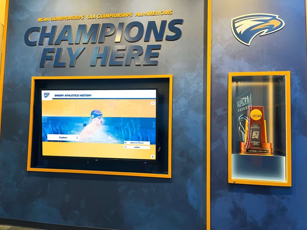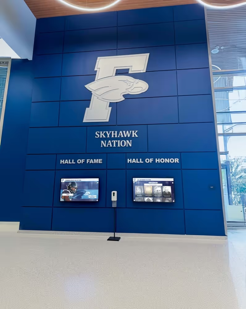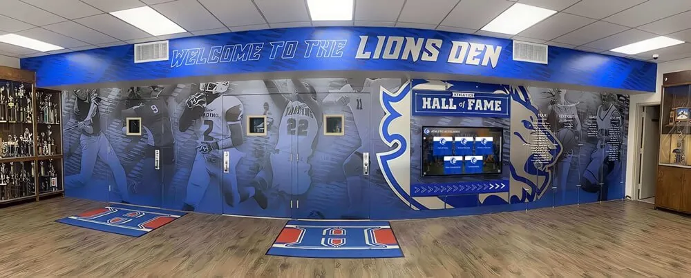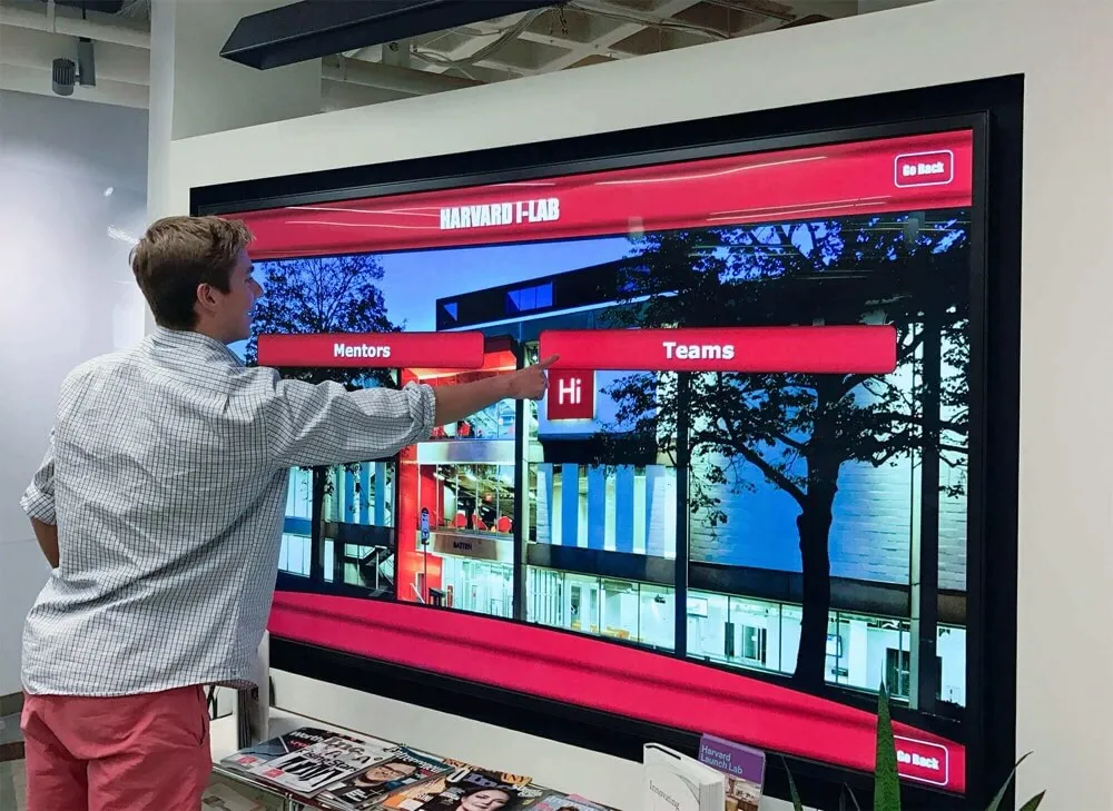


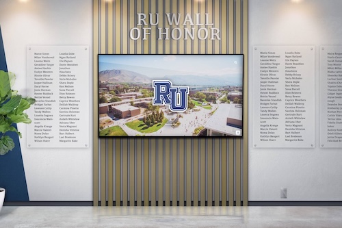
School IT teams managing recognition displays across a campus face a practical challenge that never appears in vendor pitch decks: how do you confirm that every screen is remotely controllable before a game, ceremony, or evening event—without walking to each one manually? DDC/CI (Display Data Channel / Command Interface) is the protocol that makes remote brightness, input, and power control possible, and a structured validation test is the only reliable way to know it is working before you need it.
This guide gives technology coordinators, AV directors, and recognition-program owners a repeatable procedure for testing DDC/CI control on school recognition displays. You will learn what DDC/CI is, which VCP command codes map to brightness, input, and power, what tools to use on Windows and Linux, and how to document the results so your team can act consistently whether one display fails or fifteen do.
A DDC/CI control test answers one question for each display: can centralized software read and write the monitor’s operating parameters through the video cable? If the answer is yes, your IT team can adjust brightness from a help desk, switch input sources after a network hiccup, and schedule overnight power-down without physically touching each unit. If the answer is no, you need to know that before the athletic banquet, not during it.

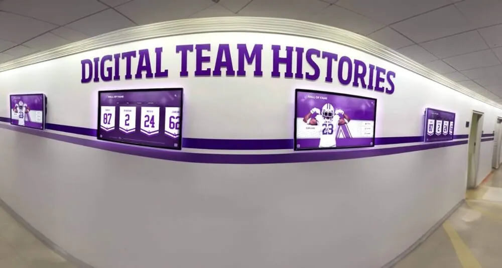
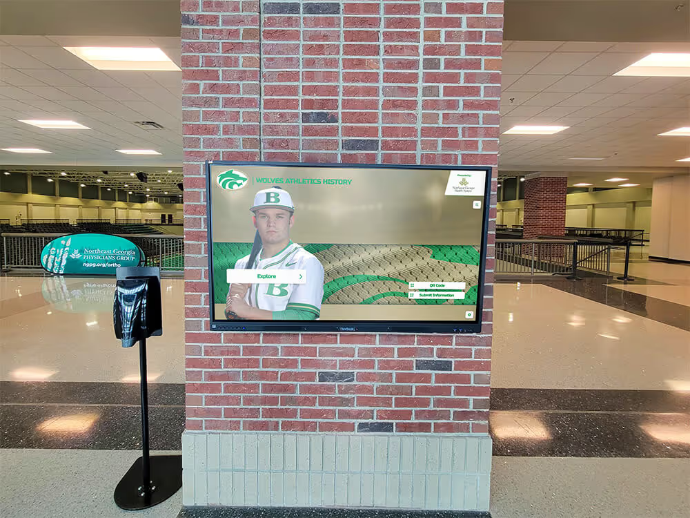
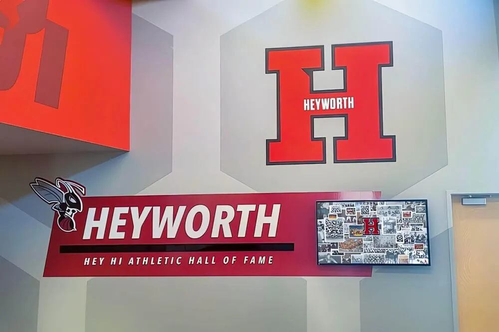
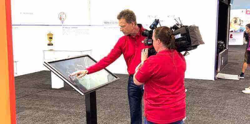
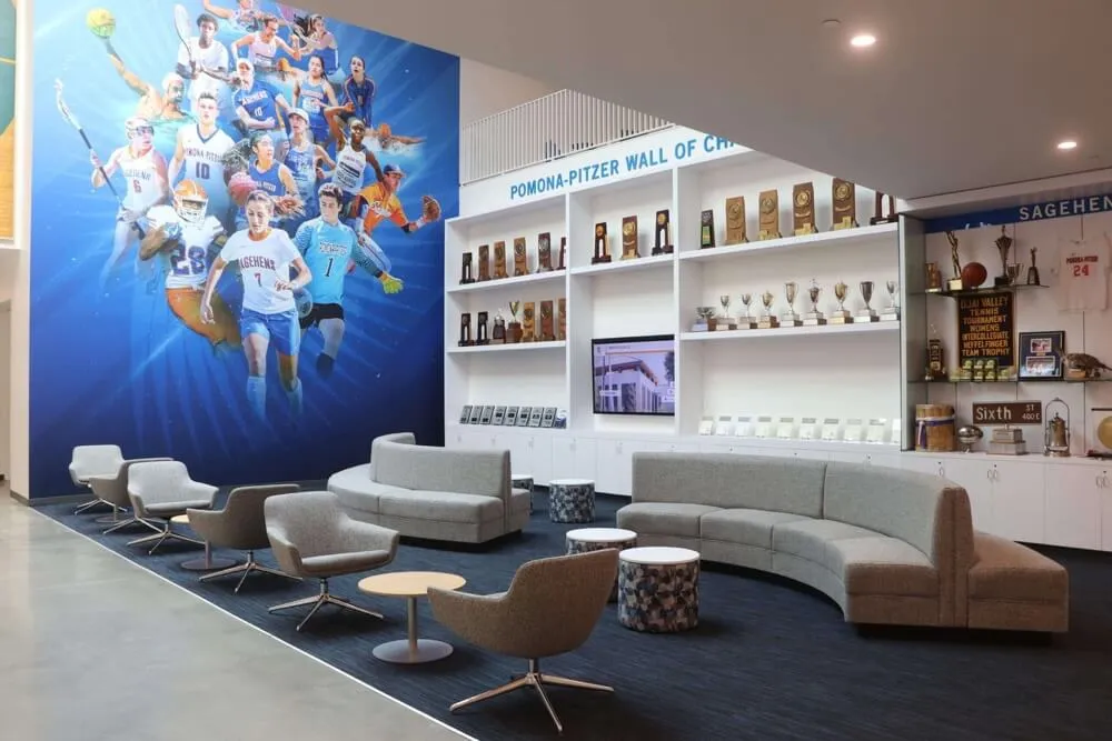
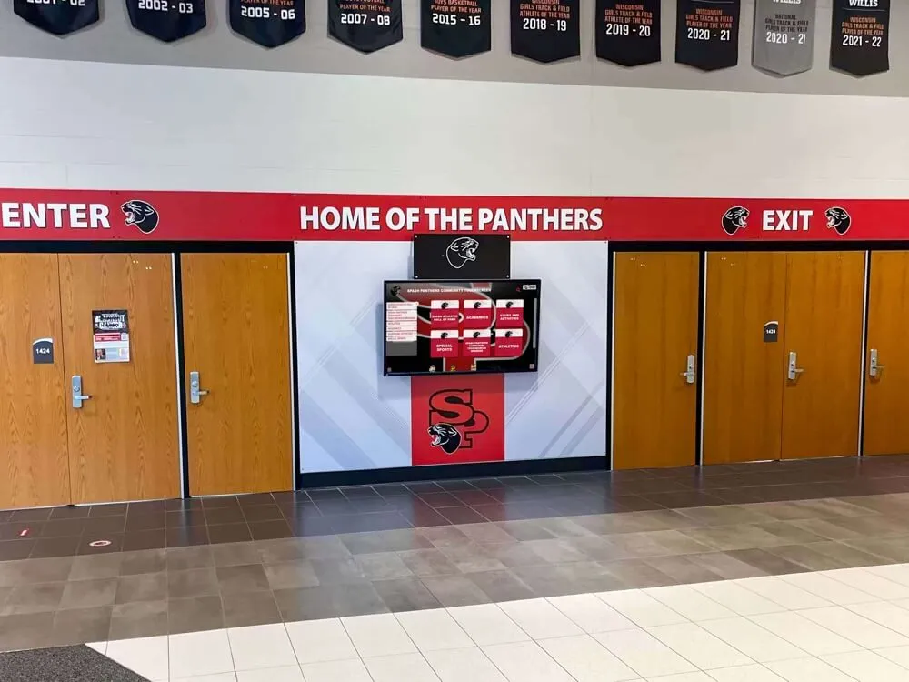
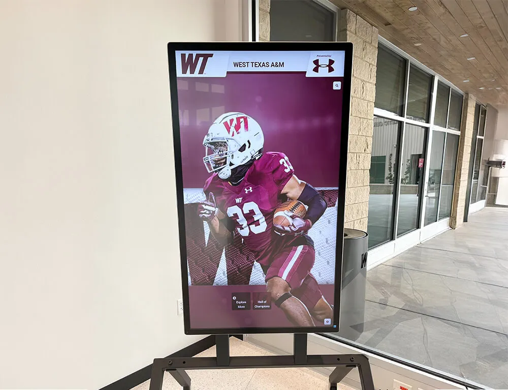
Recognition displays installed in high-traffic hallways are often difficult to reach manually—DDC/CI remote control becomes essential when screens need adjustment during an event
What DDC/CI Is and Why It Matters for Recognition Displays
DDC/CI stands for Display Data Channel / Command Interface. It is an extension of the DDC standard defined by the Video Electronics Standards Association (VESA) that adds a bidirectional communication channel between a host computer and a connected monitor. While basic DDC carries read-only identification data (the EDID block describing the display’s capabilities), DDC/CI allows the host to send commands that change the display’s operating state.
The protocol runs over the I2C bus embedded in standard video cables—VGA, DVI, HDMI, and DisplayPort all carry it. When DDC/CI is enabled on both the display and the host, software can read and write Virtual Control Panel (VCP) codes, which are standardized hex values mapping to individual monitor functions.
For school recognition displays specifically, DDC/CI matters because:
- Physical access is limited. Athletic hallway displays may be wall-mounted six feet high behind trophy cases. Library archive screens may be across campus in a restricted area. Walking to each unit to adjust brightness or cycle power is time-consuming and sometimes impractical during busy periods.
- Recognition programs run on schedules. A digital athletic recognition display needs to be at full brightness for a banquet, dimmed for an awards ceremony, and powered off overnight. Scripted DDC/CI commands can automate this sequence reliably.
- Input switching happens at inconvenient times. If a media player reboots and the display falls back to a different input, an IT team member needs a way to restore the correct source without entering the gym mid-event.
The VESA MCCS Standard
VCP codes are defined in the VESA Monitor Control Command Set (MCCS) specification, which vendors implement in varying degrees of completeness. MCCS defines dozens of codes covering brightness, contrast, input selection, power mode, color temperature, and more. Not every display implements every code—validation testing establishes exactly which codes your specific hardware responds to.
The three codes most critical for recognition display operations are:
| VCP Code (hex) | Function | Common Values |
|---|---|---|
10 | Brightness | 0–100 (percentage) |
12 | Contrast | 0–100 (percentage) |
60 | Input Select | 0x11 = HDMI 1, 0x12 = HDMI 2, 0x0F = DisplayPort, 0x01 = VGA |
D6 | Power Mode | 0x01 = On, 0x02 = Standby, 0x04 = Off |
Note that exact input select values vary by manufacturer. Some displays map HDMI 1 to 0x11, others to 0x04. Your validation test will establish the actual values your hardware reports.
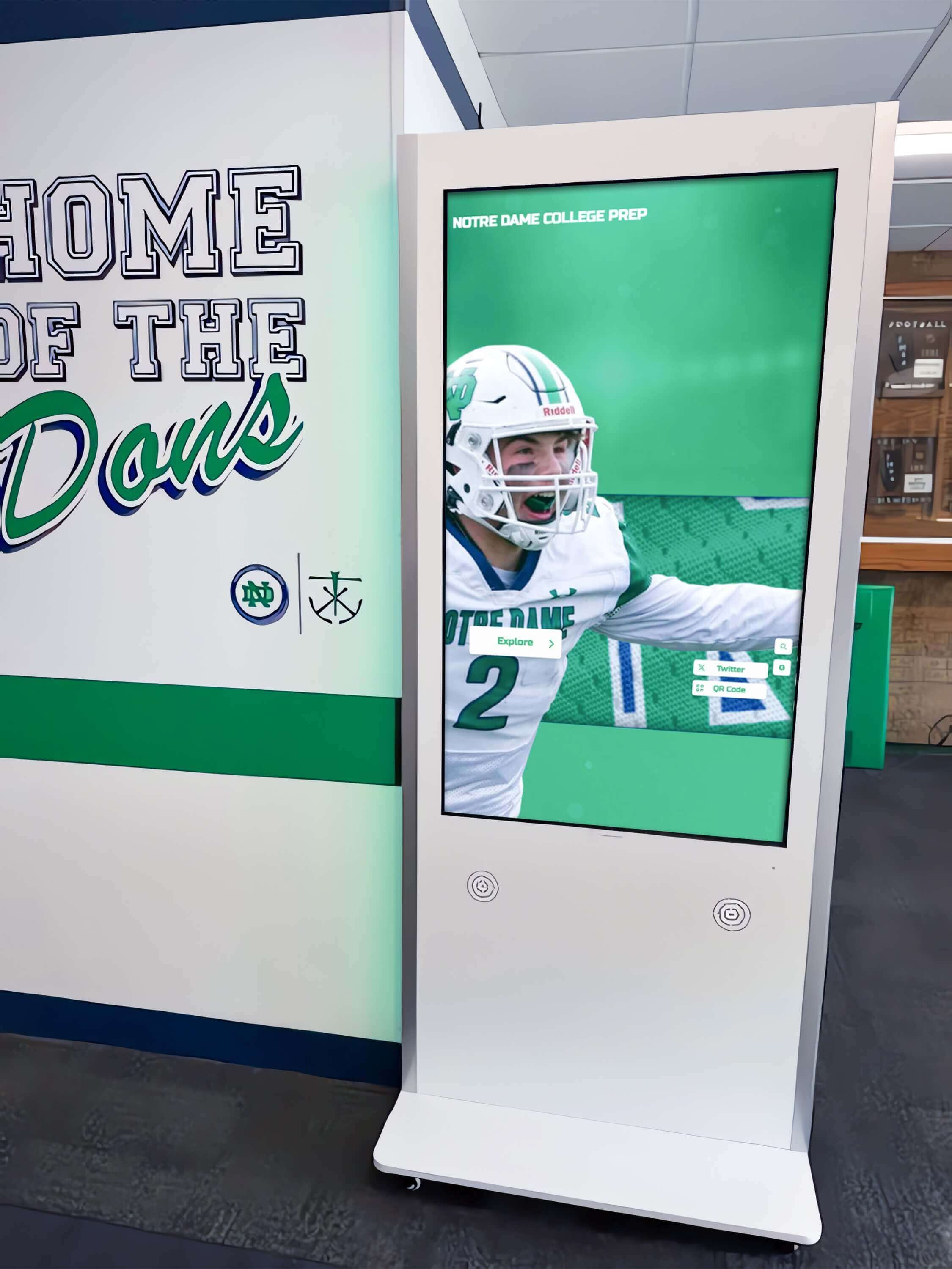
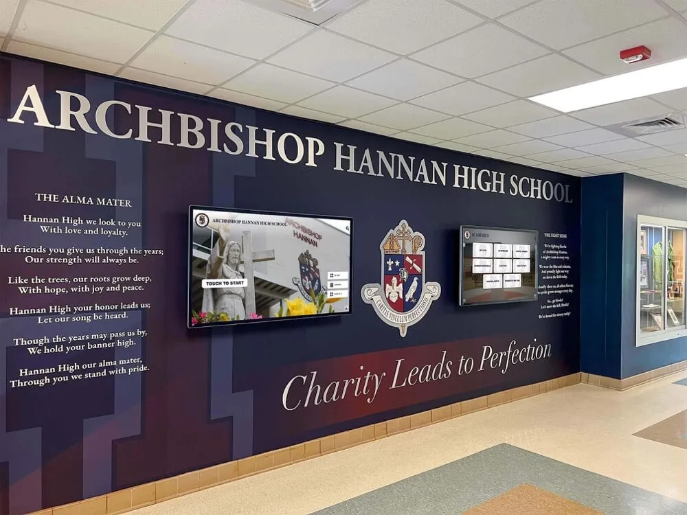
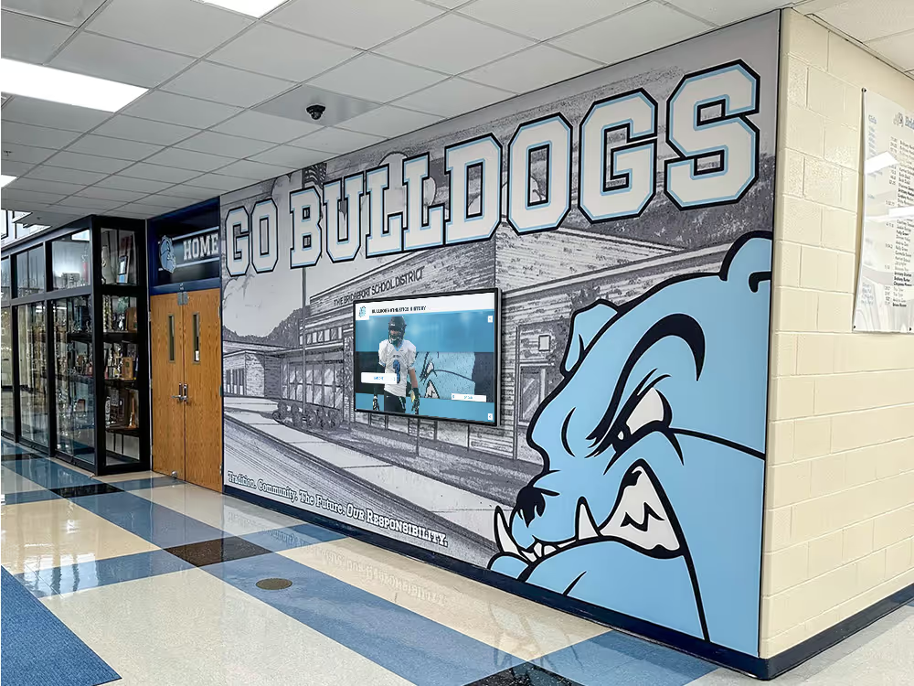
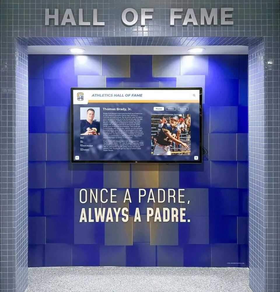
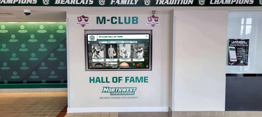
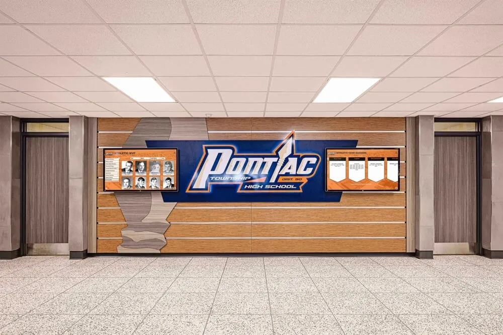
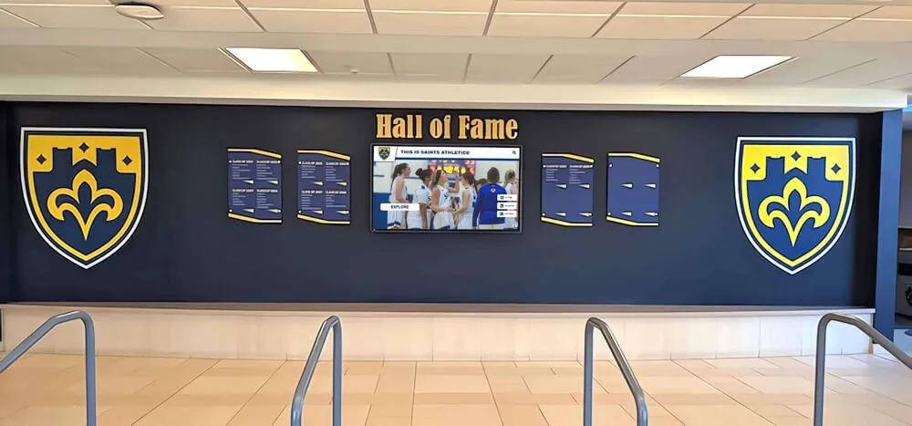
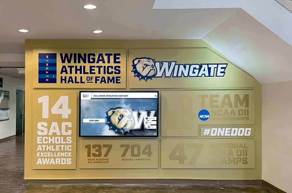
Hallway kiosks serving daily visitors benefit from automated brightness scheduling—DDC/CI makes those adjustments without staff intervention
Tools Required
Choose one of the following tools based on your operating environment. Both are well-established utilities with active communities and extensive hardware compatibility documentation.
Windows: ControlMyMonitor
ControlMyMonitor (NirSoft) is a free Windows utility that enumerates connected monitors, displays all VCP values, and allows read/write operations through a graphical interface or command-line parameters. Command-line access makes it scriptable for use in scheduled tasks, login scripts, or remote management tools.
Basic syntax for command-line control:
ControlMyMonitor.exe /SetValue "\\.\DISPLAY1\Monitor0" 10 75
This sets VCP code 10 (brightness) to 75 on the first detected monitor. Replace the display path with the identifier shown in the GUI for your specific recognition display.
For reading the current value:
ControlMyMonitor.exe /GetValue "\\.\DISPLAY1\Monitor0" 10
Linux: ddcutil
ddcutil is the standard open-source DDC/CI utility for Linux. It communicates with monitors over I2C and is available in most distribution package repositories.
Install on Debian/Ubuntu:
sudo apt install ddcutil
Detect connected displays:
ddcutil detect
Read brightness on bus 1:
ddcutil --bus 1 getvcp 10
Set brightness to 75:
ddcutil --bus 1 setvcp 10 75
List all readable VCP capabilities:
ddcutil --bus 1 capabilities
The capabilities command is particularly useful during initial validation—it returns the complete list of VCP codes the display reports as supported, which tells you before testing which functions are available.
Step-by-Step DDC/CI Control Test Procedure
Run this procedure on each recognition display as part of your initial installation commissioning or as a periodic validation check. Document results in the tracking table at the end of this section.
Prerequisites
- Display must be powered on and connected to the host computer via the production video cable (HDMI, DisplayPort, or DVI)
- DDC/CI must be enabled in the display’s OSD menu (usually found under Setup, Advanced, or System settings)
- On Windows: ControlMyMonitor downloaded and placed in a known path
- On Linux:
ddcutilinstalled; user must have I2C bus access (add user toi2cgroup or run withsudo) - Note the display’s current brightness setting before testing so you can restore it afterward
Step 1 — Confirm DDC/CI Is Enabled
Before any software test, verify the setting in the display’s on-screen display menu. The exact menu path varies by manufacturer, but common locations are:
- Samsung commercial displays: Menu → System → General → HDMI Hot Plug / DDC/CI
- LG commercial displays: Settings → General → SIMPLINK → (separate DDC/CI toggle in some models)
- NEC/Sharp commercial displays: OSD → Advanced Settings → DDC/CI
Set this to On or Enable. If the option is grayed out, check whether the display requires a specific input type to expose DDC/CI (some displays only enable it on certain ports).
Step 2 — Detect the Display
Windows: Open ControlMyMonitor. The main window lists all monitors detected. Confirm your recognition display appears with its correct model name. If it does not appear, DDC/CI communication is not established—revisit Step 1 or check cable integrity.
Linux:
sudo ddcutil detect
Successful output includes a display number, I2C bus number, and the monitor’s EDID-reported model name. If no displays appear, check that the i2c-dev kernel module is loaded (sudo modprobe i2c-dev) and that the user has I2C bus access.
Step 3 — Test Brightness Control (VCP 10)
Read current value:
- Windows:
ControlMyMonitor.exe /GetValue "\\.\DISPLAY1\Monitor0" 10 - Linux:
ddcutil getvcp 10
Record the current value. Expected output format on Linux: VCP code 0x10 (Brightness): current value = 75, max value = 100
Write a test value:
Set brightness to 50:
- Windows:
ControlMyMonitor.exe /SetValue "\\.\DISPLAY1\Monitor0" 10 50 - Linux:
ddcutil setvcp 10 50
Observe the display. The brightness should visibly decrease within 1–3 seconds. If the display does not respond, note the failure and proceed—some VCP codes may not respond while others work correctly.
Restore original value:
ddcutil setvcp 10 75 # replace 75 with the value recorded above
Pass criterion: Display brightness changed in response to the set command and the read command returned a consistent value.
Step 4 — Test Input Control (VCP 60)
Read current input:
ddcutil getvcp 60
The output identifies both the current value and the maximum supported value. Note the hex value corresponding to the currently active input—this is the value you will use to restore state.
Read capabilities to list supported inputs:
ddcutil capabilities | grep -A5 "Input Source"
This returns the manufacturer’s reported list of input codes and their labels, which eliminates guessing when input values differ from MCCS defaults.
Test switching to a second input: If your recognition display has a second HDMI port available (even if nothing is connected), send a switch command:
ddcutil setvcp 60 0x12 # HDMI 2 per MCCS default
The display should either switch input or display a “No Signal” message on that input. Either response confirms the VCP write was received and acted upon. A display that shows no change at all—including no signal-loss flash—has not responded to the command.
Restore original input:
ddcutil setvcp 60 0x11 # replace with your recorded value
Pass criterion: Display acknowledged the input change command (visible input switch or no-signal indicator on the new input).
Step 5 — Test Power Mode Control (VCP D6)
Power mode testing should be scheduled for a time when the display going dark is acceptable—typically during off-hours validation, not during school hours.
Read current power state:
ddcutil getvcp D6
Expected output when display is on: current value = 1
Send standby command:
ddcutil setvcp D6 2
The display should enter standby (backlight off while electronics remain powered). Wait 5 seconds, then restore:
ddcutil setvcp D6 1
Pass criterion: Display entered standby and returned to active state on command.
Note: Some commercial displays implement power-off (0x04) via DDC/CI but require a physical button or network command to power back on, because the DDC/CI channel itself goes dark when the display is fully powered off. Test and document your hardware’s actual behavior so your automation scripts account for it correctly.
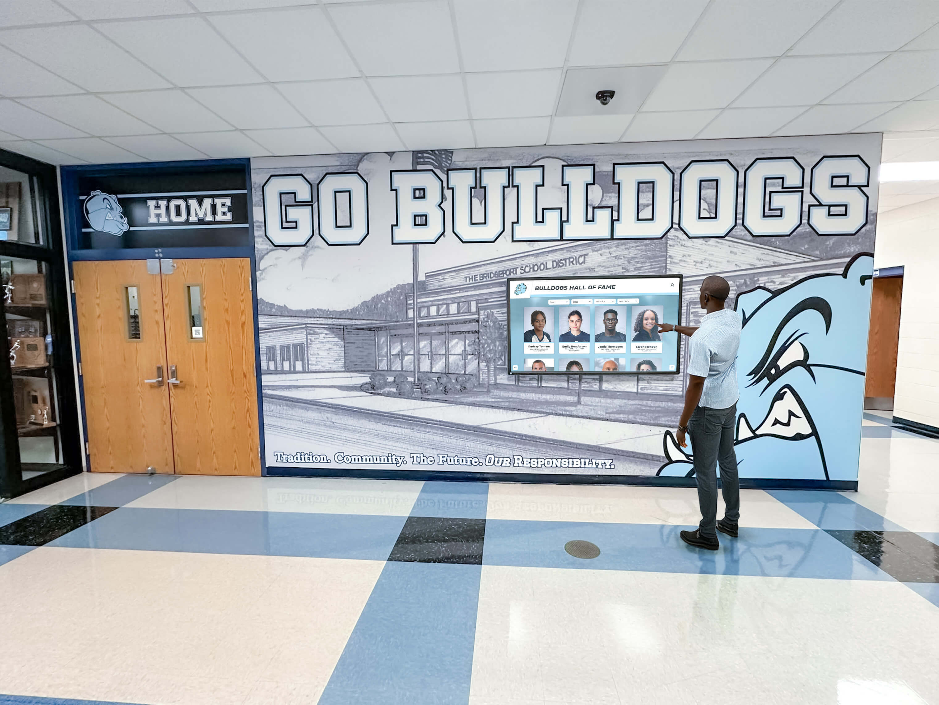
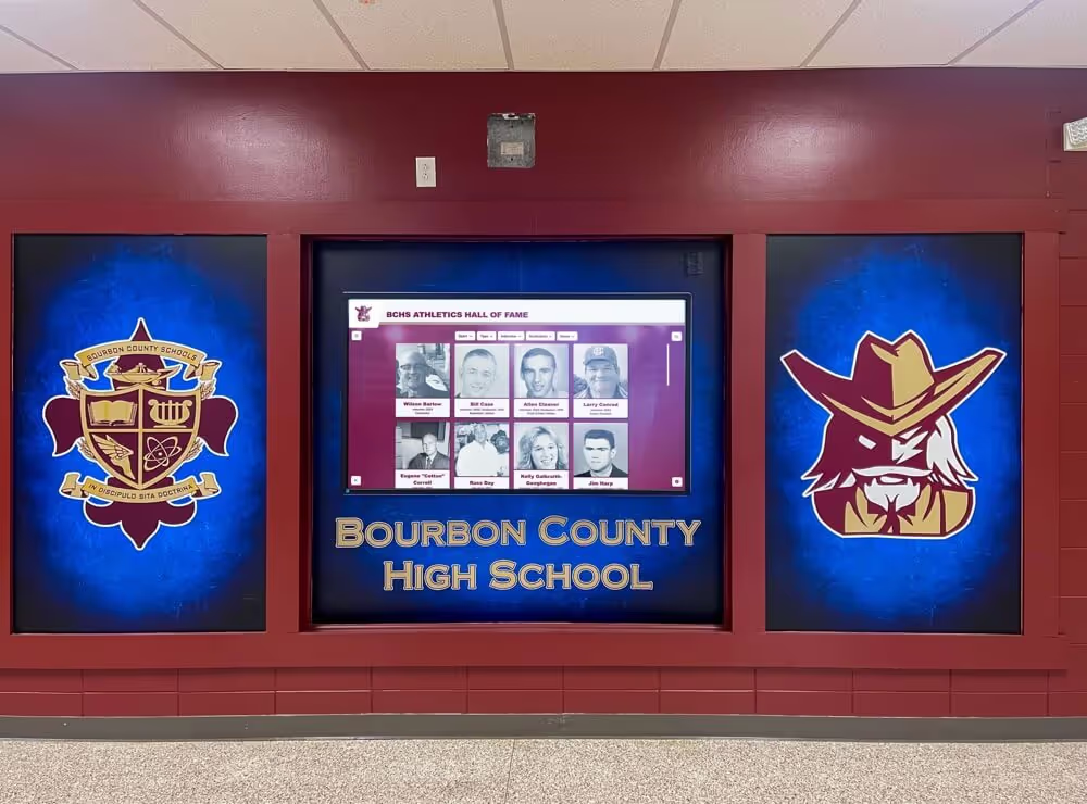
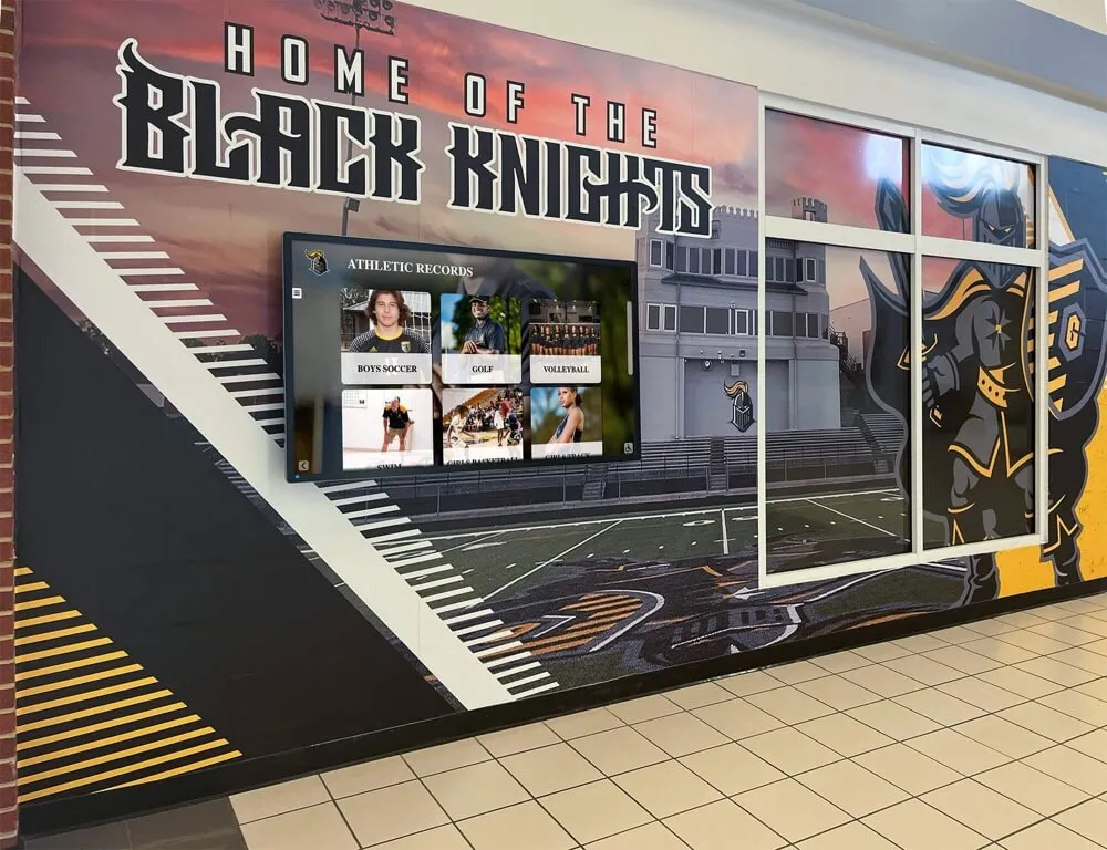
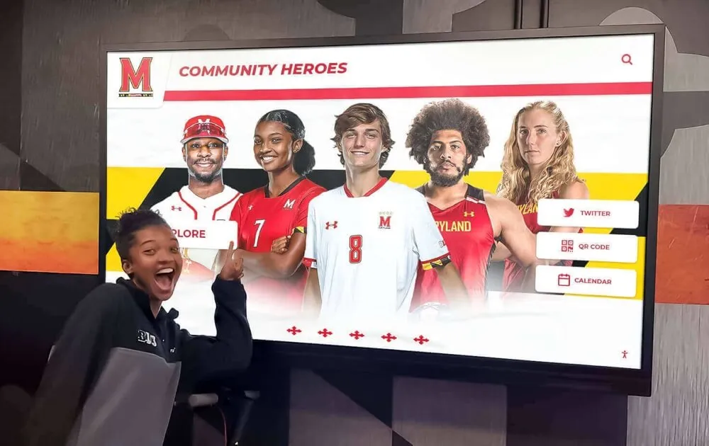
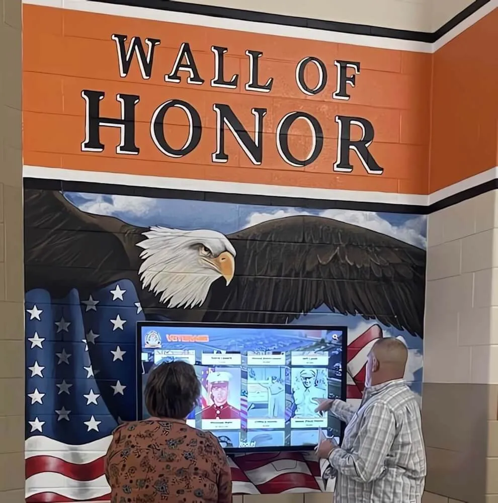
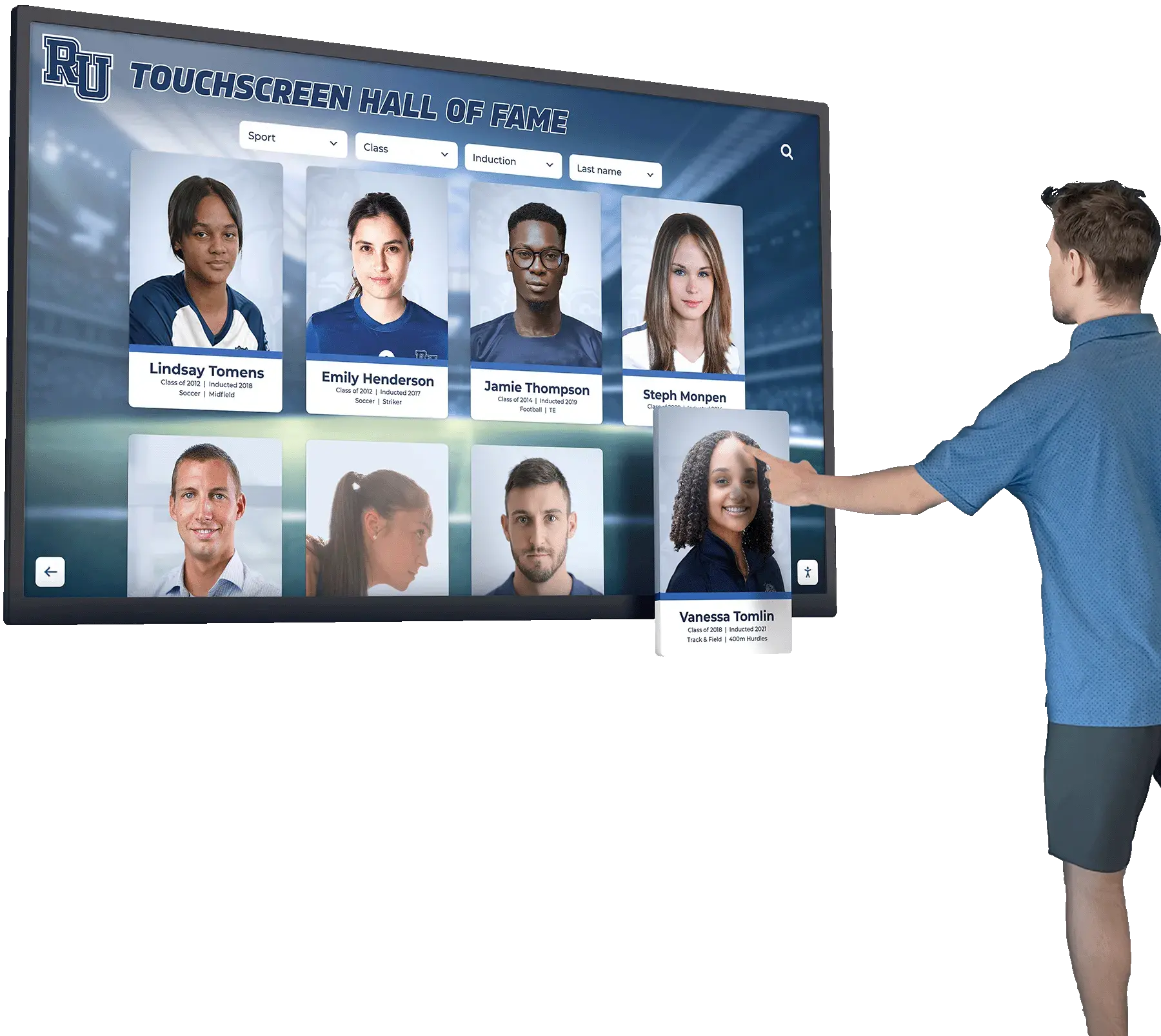
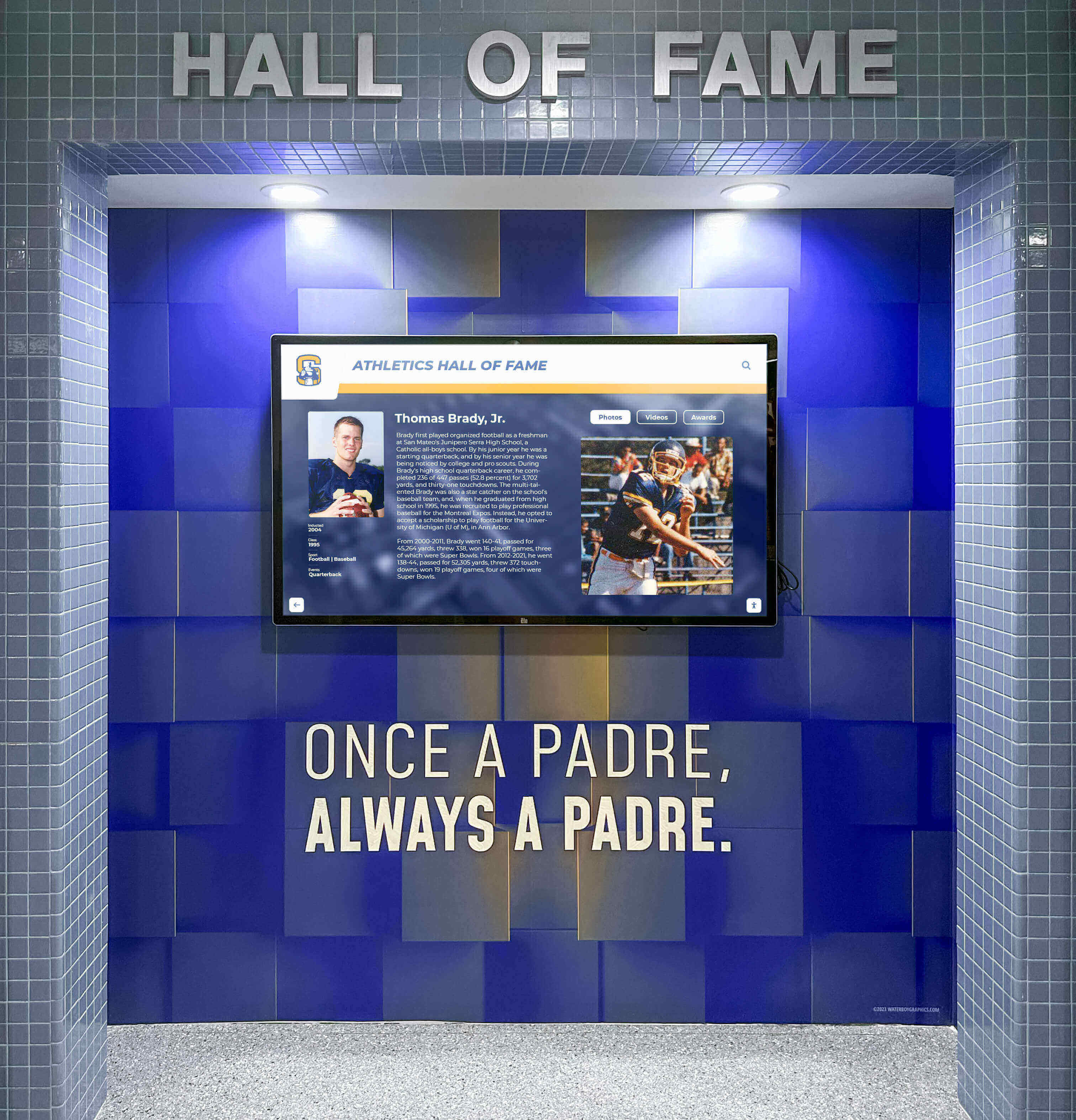
Recognition displays see regular daily use—scheduled brightness adjustment and reliable power management protect both the hardware and the visitor experience
Step 6 — Document Results
Complete one row in this tracking table for each display tested. File a copy with your AV documentation and note any displays requiring follow-up.
| Display ID | Location | Model | DDC/CI Enabled | VCP 10 (Brightness) | VCP 60 (Input) | VCP D6 (Power) | Notes |
|---|---|---|---|---|---|---|---|
| HOF-01 | Main lobby | — | Yes / No | Pass / Fail | Pass / Fail | Pass / Fail | — |
| HOF-02 | Gym entrance | — | Yes / No | Pass / Fail | Pass / Fail | Pass / Fail | — |
| HOF-03 | Athletic hall | — | Yes / No | Pass / Fail | Pass / Fail | Pass / Fail | — |
Record the firmware version from the display OSD alongside these results. Firmware updates occasionally affect DDC/CI behavior—version tracking helps correlate any future regressions.
Troubleshooting Q&A
Q: ddcutil detect shows no displays even though the monitor is connected.
Check three things in order. First, confirm the i2c-dev kernel module is loaded: lsmod | grep i2c_dev. If not, run sudo modprobe i2c-dev. Second, verify the user has read/write access to I2C bus devices: ls -la /dev/i2c-*. The user needs to be in the i2c group or the command needs sudo. Third, some HDMI-to-DisplayPort adapters do not pass DDC through—if you are using an adapter, test with a direct native cable.
Q: getvcp returns a value but setvcp has no visible effect.
The display may implement the VCP code as read-only, or there may be an OSD lock active. Check the display’s OSD for a Key Lock or OSD Lock setting and disable it. Also confirm you are targeting the correct monitor when multiple displays are connected: ddcutil --display 2 setvcp 10 50 targets the second detected display specifically.
Q: Brightness control works but input switching does not.
Input switching is one of the less consistently implemented VCP codes across manufacturers. Run ddcutil capabilities and look for the Input Source entry—if it does not appear, the manufacturer has not exposed input switching via DDC/CI on this model. In that case, input management must happen through the connected media player’s software or through a network-controlled HDMI switch upstream of the display.
Q: Power commands work during testing but the automation script fails.
DDC/CI commands have a settling time requirement between consecutive writes—the MCCS specification recommends a minimum 50ms delay between commands. Scripts that issue multiple VCP writes in rapid succession may exceed the display’s processing speed. Add a sleep or delay between commands: ddcutil setvcp D6 1 && sleep 1 && ddcutil setvcp 10 75.
Q: The display shows a different brightness during testing than expected.
Commercial recognition displays sometimes have an ambient light sensor that overrides software brightness settings. Check the OSD for an Auto Brightness or Eco Sensor setting and disable it during DDC/CI-managed operation. Otherwise the sensor will continuously correct whatever value your software sets.
Q: We have twenty displays across three buildings. How do we run this at scale?
Build a shell script or PowerShell script that loops through each display’s host computer IP, uses SSH or PsExec to run the ddcutil or ControlMyMonitor commands remotely, and writes results to a shared log file. Many schools use this approach as part of their morning display health check, verifying brightness and power state automatically before the first bell.
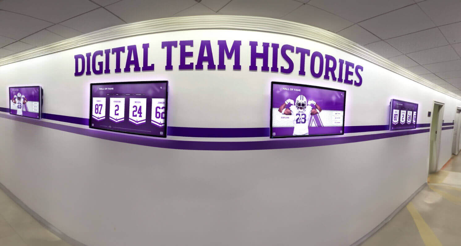
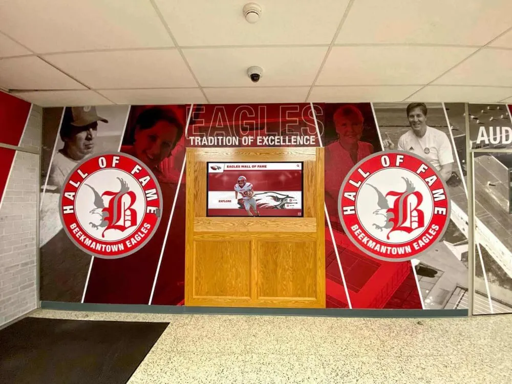
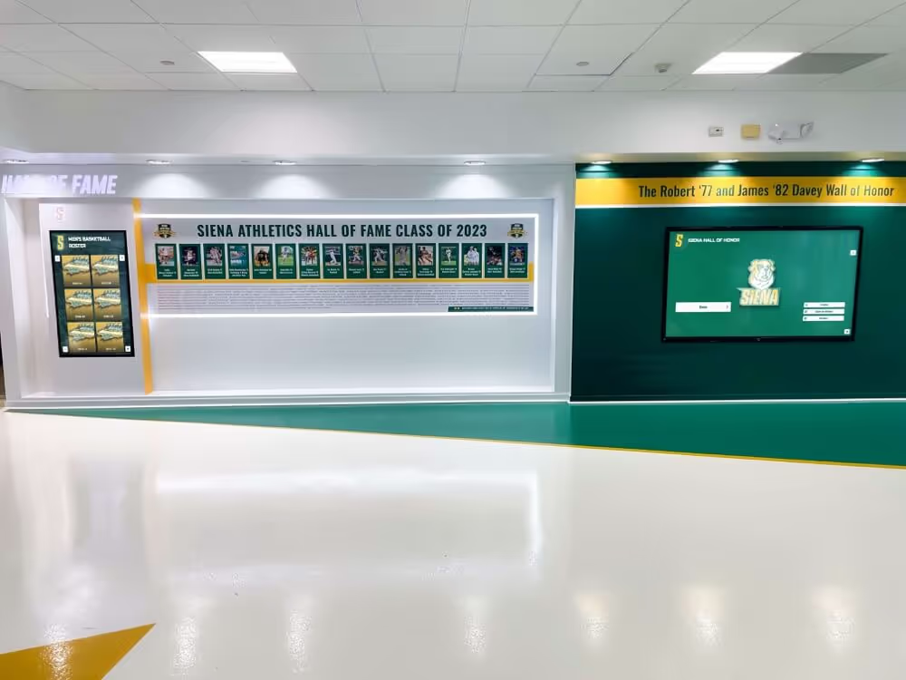
Multi-display hallway installations benefit most from centralized DDC/CI management—one script can verify and correct all screens simultaneously
Connecting DDC/CI Management to Recognition Program Workflows
DDC/CI control is not a standalone IT task—it integrates directly into how recognition programs operate day to day.
Brightness Scheduling for Events and Ceremonies
School recognition displays should run at different brightness levels depending on context. A lobby display during a Tuesday afternoon might run at 60% to preserve backlight life and avoid glare on adjacent trophy cases. The same display during an induction ceremony needs to be at 100% so guests thirty feet away can read inductee names clearly.
A scheduled task or cron job can handle this automatically using the VCP 10 test values you validated:
- 7:00 AM: Set brightness to 70 (normal school day)
- 6:00 PM on event days: Set brightness to 100 (evening recognition events)
- 10:00 PM: Set power mode to standby
This operational pattern extends display life by reducing unnecessary brightness while ensuring peak performance when recognition programs rely on the screen. Well-managed display schedules also support the kind of academic recognition programs that school administrators want to run consistently without adding staff time to every event.
Input Source Consistency for Athletic Archives
Recognition displays connected to dedicated media players should consistently show the correct input source. If the media player is on HDMI 1 and a power cycle causes the display to default to HDMI 2, the screen goes dark at exactly the wrong moment—when a family is visiting to see their student’s archived achievement or when an athletic fundraiser is running.
A startup script on the media player can issue a VCP 60 command at boot to assert the correct input source before launching recognition software. This eliminates the category of support calls that begin with “the hall of fame screen is showing a blue screen.”
For schools building or refreshing athletic recognition archives, the guide on digitizing and archiving team photos walks through the content side of the workflow that feeds these displays.
Power Management for Multi-Venue Deployments
Schools with recognition displays in gymnasiums, natatoriums, fieldhouses, and auxiliary gyms may run displays only on days when those facilities are in use. DDC/CI power commands integrated with facility scheduling software can power displays on when a room is reserved and off when it is not, without requiring facilities staff to enter each space manually.
This approach pairs naturally with broader recognition program infrastructure. Schools running comprehensive academic recognition programs across multiple spaces need display management to be automatic rather than manual so that recognition stays visible without adding operational overhead.
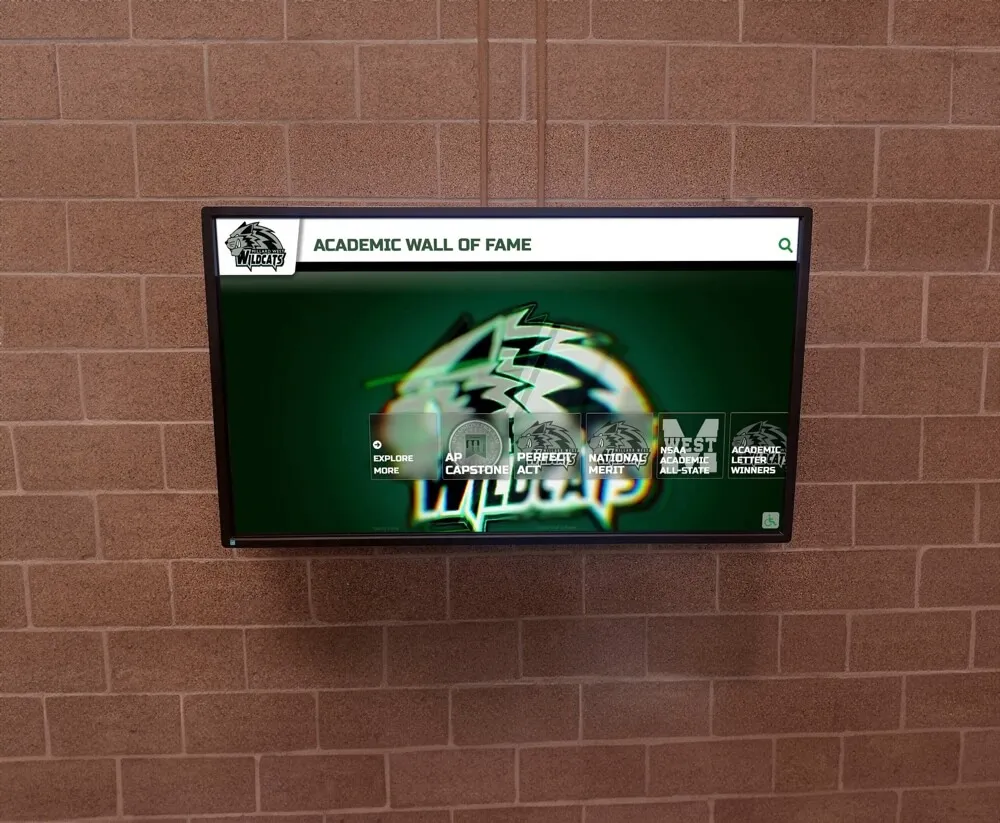
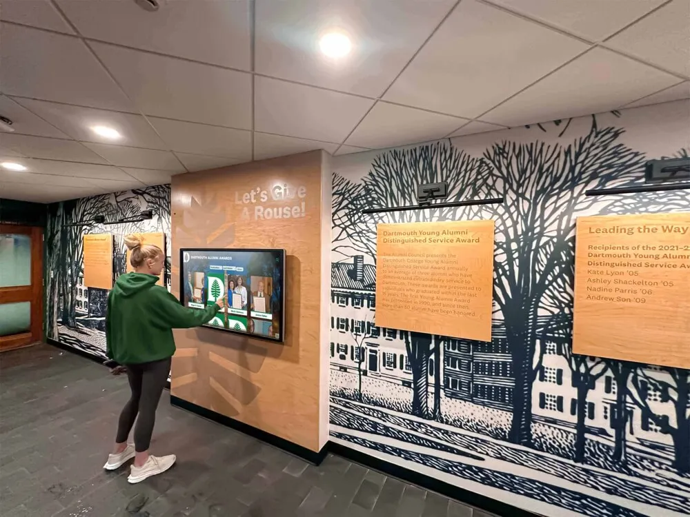
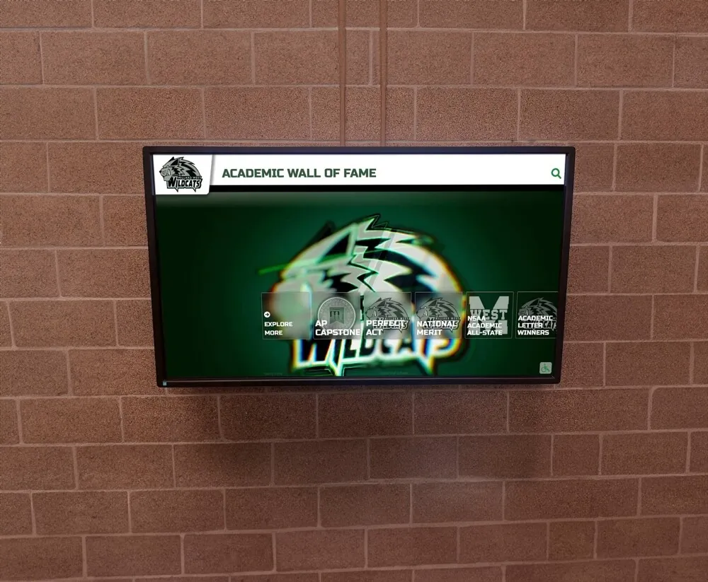
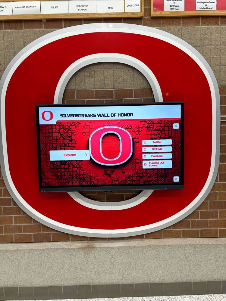
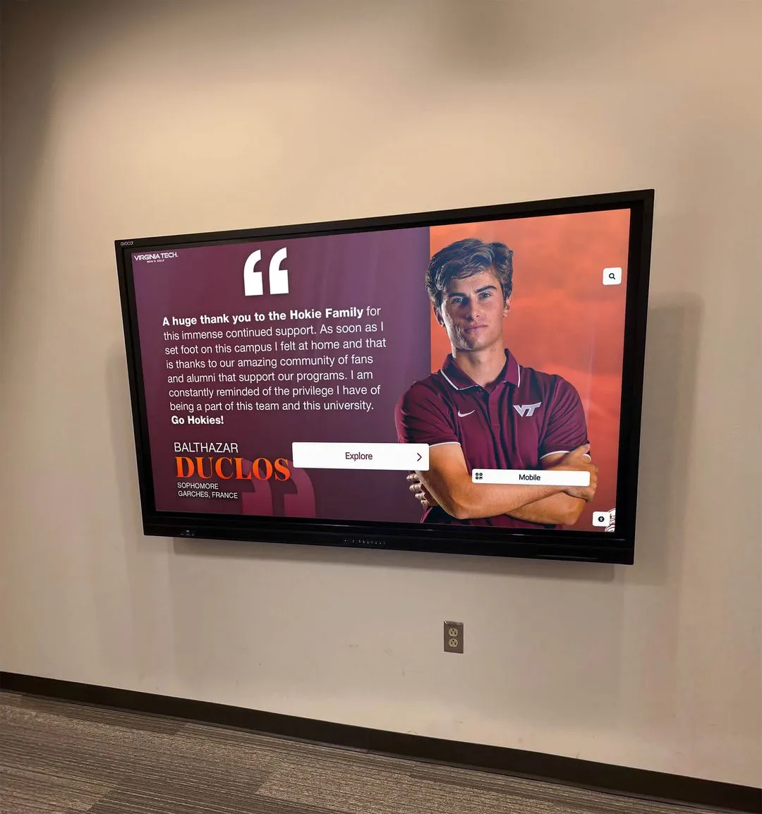
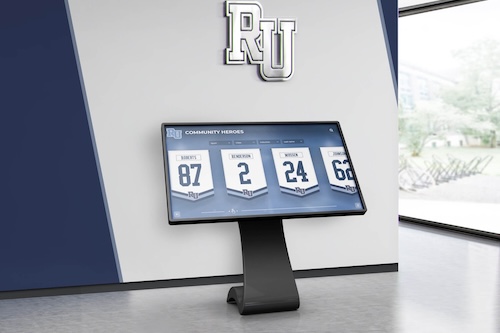
Academic recognition displays in hallways benefit from the same DDC/CI power and brightness management as athletic displays—consistent operational standards serve all recognition programs equally
Display Selection Considerations for DDC/CI Compatibility
If your school is selecting new recognition displays, DDC/CI support should be an explicit requirement in your procurement specification. Not all commercial displays implement DDC/CI equally, and consumer-grade screens frequently omit it entirely.
Procurement Checklist
When evaluating displays for recognition program use, confirm the following with the vendor or through a pre-purchase test:
| Requirement | Verification Method |
|---|---|
| DDC/CI enabled by default or easily enabled in OSD | Check OSD menu at vendor demo |
| VCP 10 (Brightness) read and write supported | Run ddcutil getvcp/setvcp during demo |
| VCP 60 (Input Select) read supported | Run ddcutil capabilities during demo |
| VCP D6 (Power Mode) write supported | Run ddcutil setvcp during demo |
| MCCS version 2.1 or higher | ddcutil capabilities output shows version |
| DDC/CI available on production input port | Test on HDMI 1 specifically, not just VGA |
| Firmware update does not disable DDC/CI | Ask vendor directly; note firmware version |
Commercial displays from established AV manufacturers—the same category used for corporate digital signage and command centers—typically have stronger DDC/CI implementation than consumer televisions repurposed as signage displays.
Why This Matters for Long-Term Recognition Programs
Recognition displays installed in schools today may serve the same institution for ten or more years. Athletic alumni recognition walls accumulate decades of content that makes the display itself a permanent fixture rather than a replaceable technology asset. Selecting hardware with robust DDC/CI support from day one avoids the situation where an aging display cannot be centrally managed because the IT team never validated the capability during installation.
The validation test in this guide takes approximately twenty minutes per display. Running it at installation creates a documented baseline. Running it again after firmware updates confirms nothing changed. And running it before major recognition events—homecoming, athletic banquets, induction ceremonies—confirms the systems your program depends on are ready.
For schools just beginning to build out recognition infrastructure, the alumni advice program blueprint provides context on the institutional side of building programs that recognition displays serve.
Automating DDC/CI Validation Across Multiple Displays
Once you have validated DDC/CI on individual displays, the next step is automating that validation as part of regular maintenance. A simple script that runs weekly can catch regressions before they affect events.
Linux example (bash):
#!/bin/bash
# Run on each display's host computer; log results centrally

DISPLAY_ID="HOF-01"
LOG_FILE="/var/log/ddc-validation.log"
DATE=$(date '+%Y-%m-%d %H:%M')

# Read brightness
BRIGHTNESS=$(ddcutil getvcp 10 2>/dev/null | grep -oP 'current value = \K[0-9]+')

# Read input
INPUT=$(ddcutil getvcp 60 2>/dev/null | grep -oP 'current value = \K[0-9]+')

echo "$DATE,$DISPLAY_ID,brightness=$BRIGHTNESS,input=$INPUT" >> "$LOG_FILE"
Run this via cron on each display’s attached host, then aggregate the log files on a central monitoring server. Gaps in the log (display not responding to DDC) or unexpected values (brightness at 0 during school hours) generate alerts without manual inspection.
Windows example (PowerShell):
$displayPath = "\\.\DISPLAY1\Monitor0"
$controlTool = "C:\Tools\ControlMyMonitor.exe"

$brightness = & $controlTool /GetValue $displayPath 10
$inputSrc = & $controlTool /GetValue $displayPath 60

"$(Get-Date),HOF-01,brightness=$brightness,input=$inputSrc" |
  Out-File -Append -FilePath "C:\Logs\ddc-validation.csv"
Schedule this in Task Scheduler to run daily before school starts. A centralized share or monitoring platform collects the CSVs and surfaces anomalies.
Integrating with Recognition Program Calendars
For schools running formal recognition programs with scheduled events—annual athletic fundraisers, induction nights, senior recognition events—a calendar-aware script can adjust display parameters automatically based on event type.
An event-night profile might:
- Set brightness to 100 (VCP 10)
- Assert the correct media player input (VCP 60)
- Verify power state is active (VCP D6)
- Log all three results with a timestamp tied to the event name
This gives program coordinators a record that the display was properly configured for each event, useful both for troubleshooting and for demonstrating due diligence in system management.
For schools whose recognition programs span visual identity assets like athletic logos and cheer team graphics alongside display hardware, DDC/CI management is one layer of a broader content-and-hardware workflow that keeps all the pieces in sync.

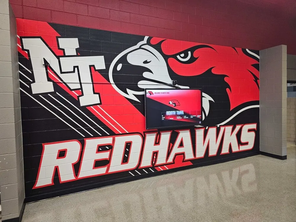
Recognition displays integrated with permanent school murals represent long-term institutional investments—validated DDC/CI control protects that investment with reliable remote management
Frequently Asked Questions
Does DDC/CI work over wireless or network connections?
DDC/CI runs over the physical video cable between the host computer and the display—it is not a network protocol. Remote management works by sending commands to the host computer (via SSH, RDP, or a remote management platform), which then relays DDC/CI commands through the local video cable to the attached display. Displays on network-controlled HDMI matrix switches may need DDC/CI passthroughs enabled in the switch firmware.
Can DDC/CI damage a monitor?
Sending valid VCP codes within their documented ranges will not damage a display. The protocol is read/write within defined parameters—you cannot send a display a voltage it was not designed for. The main risk is sending an unexpected input-select code that makes the display appear broken (showing “No Signal”) when it has simply switched to an unoccupied input. Always record current values before testing and restore them afterward.
Does DDC/CI work when the display is in screen-saver or sleep mode?
Behavior varies by display. Most commercial displays respond to DDC/CI commands in standby mode (backlight off, electronics on)—this is how an wake-on-DDC workflow functions. Displays in a deeper power-off state may not respond until they receive a physical power signal. Document your hardware’s actual behavior during validation testing rather than assuming.
What if the display vendor’s software conflicts with ddcutil or ControlMyMonitor?
Some display vendors provide proprietary management software that communicates via DDC/CI at system startup. If that software is running simultaneously with ddcutil, you may get I2C bus conflicts resulting in failed reads. Test ddcutil with vendor management software closed. For production use, either rely on the vendor’s software if it meets your automation needs, or disable it and manage exclusively through ddcutil.
How often should we run the DDC/CI validation test?
Run the full procedure at initial installation (creating your baseline), after any display firmware update, and before any major recognition event. For high-priority displays—main lobby, gymnasium entrance—add a lightweight automated check (brightness read-only, no writes) to your weekly IT monitoring routine.
Recognition programs give schools a way to honor generations of students, athletes, and community members. The technology that displays those programs deserves the same careful commissioning and ongoing verification that any critical school system receives. A DDC/CI control test is twenty minutes of validation that protects years of recognition effort.
See how Rocket Alumni Solutions manages recognition display content and hardware coordination for schools.