


A school recognition display that worked perfectly at installation can go dark weeks or months later for a reason that has nothing to do with the software: the HDBaseT link has degraded. HDBaseT extends HDMI signals over a single Cat5e, Cat6, or Cat6A cable for distances up to 100 meters—making it the standard method for routing recognition display content from a rack-mounted media player to a lobby kiosk, athletic hallway screen, or donor wall panel. When the link loses integrity—because of a too-long cable run, a damaged connector, a firmware mismatch between transmitter and receiver, or a PoHDBaseT power imbalance—the display goes black or flickers with no error message that points directly to the cause.
This school recognition display HDBaseT link test checklist gives AV coordinators, IT directors, and facilities staff a structured diagnostic sequence for isolating and resolving HDBaseT signal failures. Work through the steps in order so each test builds on the last. Every step is safe to run without specialist tools; the escalation table at the end identifies the situations that warrant calling a licensed AV integrator or contacting the equipment vendor.
Quick answer: To test HDBaseT link integrity on a school recognition display, (1) bypass the extender with a direct HDMI cable to confirm the source and display are working, (2) inspect the Cat cable for correct category rating, connector seating, and run length under 100 m, (3) check transmitter/receiver link LEDs, (4) verify PoHDBaseT power delivery, (5) update transmitter and receiver firmware, and (6) swap in a known-good extender set if steps 1–5 pass but the fault persists. Document the result before the next event so any team member can act on a future failure without starting from scratch.

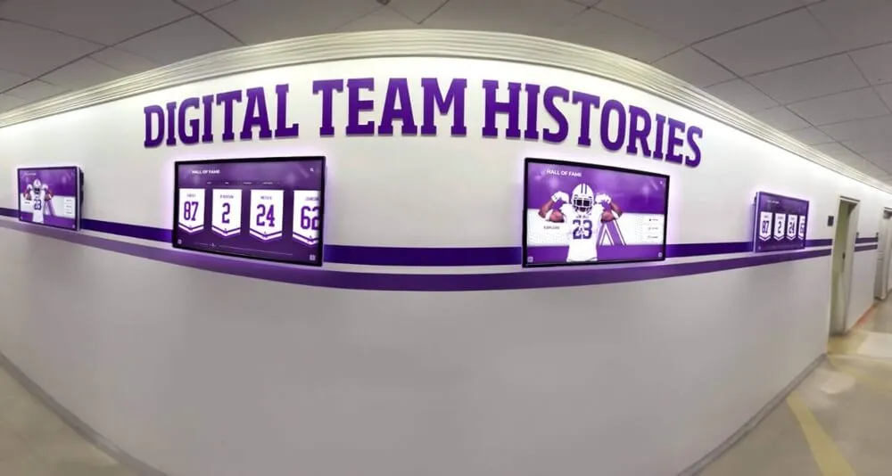
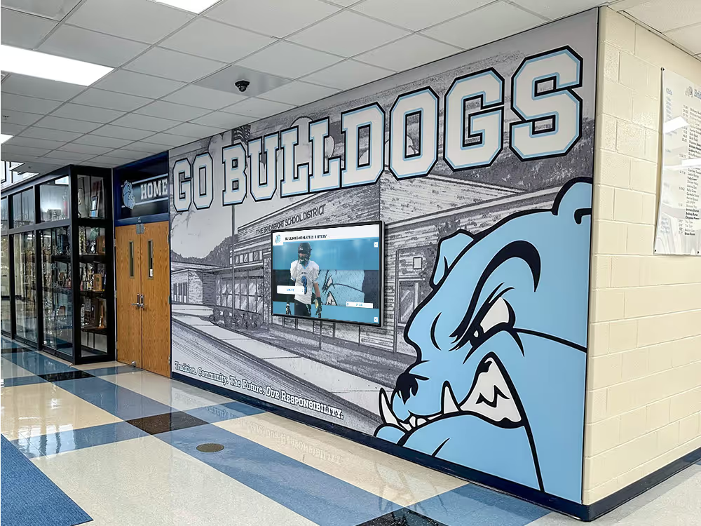
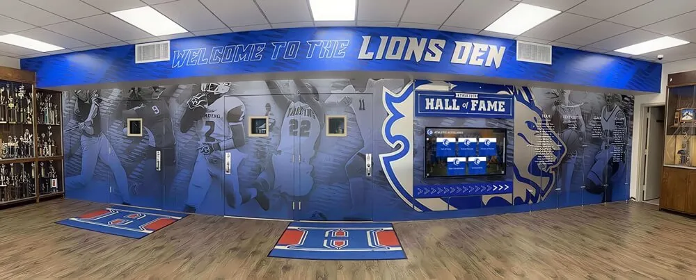
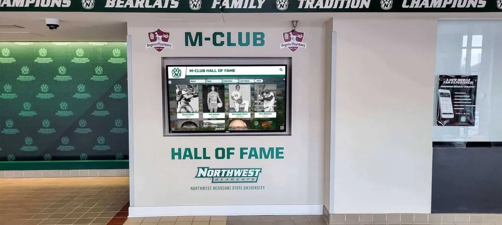
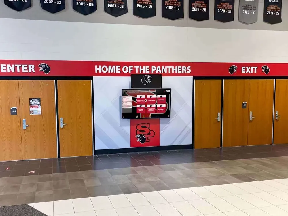
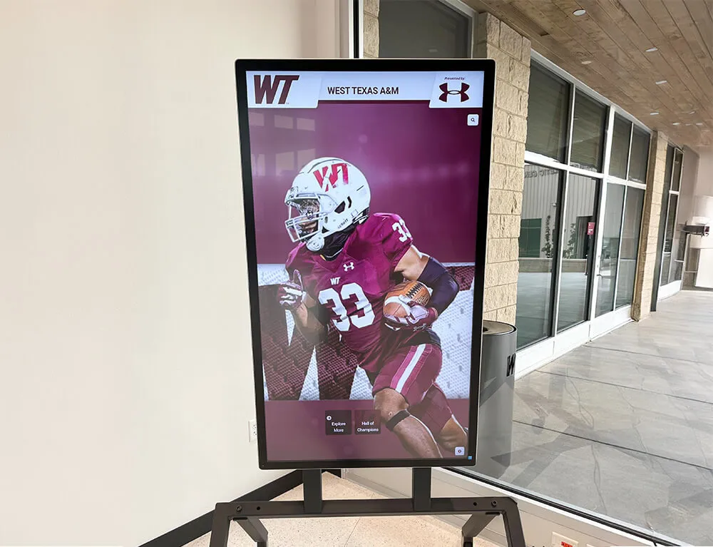
Hallway recognition displays are almost always fed by an HDBaseT extender link—a reliable link keeps the display on for every student, parent, and visitor who passes by
What HDBaseT Is and Why It Matters for Recognition Displays
HDBaseT is an industry standard (developed by the HDBaseT Alliance) for transmitting uncompressed HDMI video, audio, Ethernet, control signals (RS-232 or IR), and power over a single Category cable. Unlike HDMI cables, which reliably carry signal only to about 15 feet before signal degradation begins, HDBaseT reaches 100 meters (approximately 328 feet) at full 1080p and up to 70 meters at 4K—enough to cross an entire school building from a single rack location.
For school recognition displays, HDBaseT matters because the media player that runs the recognition platform almost never lives inside or immediately behind the display. It sits in a rack room, AV closet, or IT cabinet, and the signal travels through conduit to the lobby, trophy hallway, or gymnasium entrance where the display is mounted. That run can easily reach 50–80 meters in a large school building, putting the installation well within HDBaseT range but also well beyond what passive HDMI can do.
The components in a typical school recognition display HDBaseT installation:
| Component | Role | Failure Mode |
|---|---|---|
| Media player / PC | Generates the HDMI video signal | Source signal loss |
| HDBaseT transmitter (TX) | Converts HDMI to HDBaseT signal on Cat cable | Link training failure, firmware bug |
| Cat5e / Cat6 / Cat6A cable | Carries HDBaseT signal up to 100 m | Length exceeded, damaged pairs, bad termination |
| HDBaseT receiver (RX) | Converts HDBaseT back to HDMI | EDID mismatch, power starvation, firmware bug |
| Recognition display / monitor | Shows the content | HDCP incompatibility, input selection |
When any link in this chain fails, the result looks identical from the front of the display: a black screen or intermittent flicker. The checklist below isolates which component is responsible.
Symptom and Most Likely Cause Table
Match the symptom to the most probable cause before opening any equipment cabinet. This narrows the relevant steps.
| Symptom | Most Likely Cause | Where to Start |
|---|---|---|
| Solid black screen, display has power | HDBaseT link not training | Step 3 (LED check), then Step 4 (direct-connect test) |
| Intermittent flickering or signal dropout | Marginal cable run, bad connector, or EMI | Step 1 (cable inspection), Step 2 (run length) |
| Video appears for a few seconds then drops | PoHDBaseT power insufficient | Step 6 (power delivery) |
| No signal after power cycle | Wrong power-on sequence | Step 5 (power sequence) |
| 4K content fails, 1080p works | Cable category insufficient for 4K bandwidth | Step 2 (cable rating) |
| Black screen after extender firmware update | Firmware mismatch between TX and RX | Step 8 (firmware) |
| Display works only at shorter cable lengths | Run length exceeding cable category limit | Step 2 (run length) |
| Ethernet or control channel lost, video OK | HDBaseT link trained at reduced profile | Step 7 (link profile) |
| Signal works on one display, not another | EDID negotiation failure | Step 9 (EDID) |
HDBaseT Link Integrity Checklist
Work through every applicable step in order. Mark each step Pass, Fail, or Not Applicable before moving to the next. Stop when you find the failure—you have isolated the fault.
Step 1 — Visual Cable and Connector Inspection
Goal: Eliminate physical damage before testing any electronics.
- Trace the Cat cable from the transmitter to the receiver. Look for kinks, sharp bends, staple damage, or sections where the cable is pinched under a door threshold or furniture.
- Inspect both RJ-45 connectors at the transmitter and receiver ends. Look for bent pins, cracked connector housings, or connectors that are not fully seated in the port (they should click in).
- If the cable runs through conduit, check whether it shares conduit with high-voltage electrical runs. HDBaseT signal on Cat cable is susceptible to electromagnetic interference (EMI) from adjacent power wiring; separation of at least 2 inches from unshielded power cables is standard practice.
- Check whether the cable has been patched through a patch panel. Each patch panel hop adds insertion loss and an additional connector that must be crimped correctly. A poor-quality patch panel connection is a common source of intermittent HDBaseT failures.
- If any physical damage is found, replace the cable or connector before continuing to electronic tests.
Step 2 — Verify Cable Category and Run Length
Goal: Confirm the installed cable meets the HDBaseT bandwidth and distance requirements for the content being displayed.
HDBaseT performance varies by cable category and run length:
| Cable Category | Max Run (1080p / HDBaseT Class A) | Max Run (4K / HDBaseT 2.0) | Notes |
|---|---|---|---|
| Cat5e | 70 m | Not recommended | Marginal for long runs at 1080p |
| Cat6 | 100 m | 70 m | Standard choice for most installations |
| Cat6A | 100 m | 100 m | Recommended for 4K and future-proofing |
| Cat7 | 100 m | 100 m | Shielded; use with shielded HDBaseT hardware |
- Measure or obtain the documented run length from the transmitter port to the receiver port, including any patch panel segments.
- Verify the measured length is under the limit for your cable category and content resolution. A run measured at 95 meters on Cat5e at 1080p is at the margin—small connector quality variations can push it over the limit.
- If the run exceeds the cable category limit, either replace the cable with a higher category or add a mid-span HDBaseT repeater (a device that regenerates the signal at an intermediate point).
- Confirm the cable is a solid-core conductor, not stranded. Stranded patch cable is not rated for in-wall HDBaseT runs and will not reach the rated distance reliably.
Note for school buildings: Older school facilities often have pre-existing Cat5e installed during an earlier network upgrade. If the recognition display was installed without replacing the in-wall cable, the Cat5e run length limit may explain why a 4K-capable display shows no signal—the cable cannot carry 4K HDBaseT bandwidth at long distances.
Step 3 — Check Transmitter and Receiver Link LEDs
Goal: Use the extender hardware’s own status indicators to confirm whether the HDBaseT link has trained.
Most HDBaseT transmitters and receivers include status LEDs on the hardware. LED labels vary by manufacturer, but the common indicators are:
| LED Label | What It Means When Lit Solid | What It Means When Flashing or Off |
|---|---|---|
| LINK / LNK | HDBaseT link between TX and RX is established | Link not trained—check cable and connectors |
| HDMI IN (TX) | HDMI source signal detected at transmitter | No source signal—check media player output |
| HDMI OUT (RX) | HDMI signal being delivered to display | No output—link may not be trained |
| PWR / POWER | Unit has power | No power—check power supply or PoHDBaseT |
| PoE / PoH | PoHDBaseT power is being delivered | Power issue at the powered end |
- Observe the LINK LED on both the transmitter and receiver with the full cable run connected. If the LINK LED is off on either unit, the HDBaseT link has not trained—proceed to Steps 4 and 5.
- If the transmitter shows HDMI IN but no LINK, the problem is in the HDBaseT cable segment or the receiver. Proceed to Step 4.
- If both units show LINK solid but the display still shows black, the problem is downstream of the receiver—check HDMI cable from receiver to display, input selection on the display, or HDCP compatibility.
- Photograph or record the LED states before changing any cables—this documents the state of the link at the time of failure.
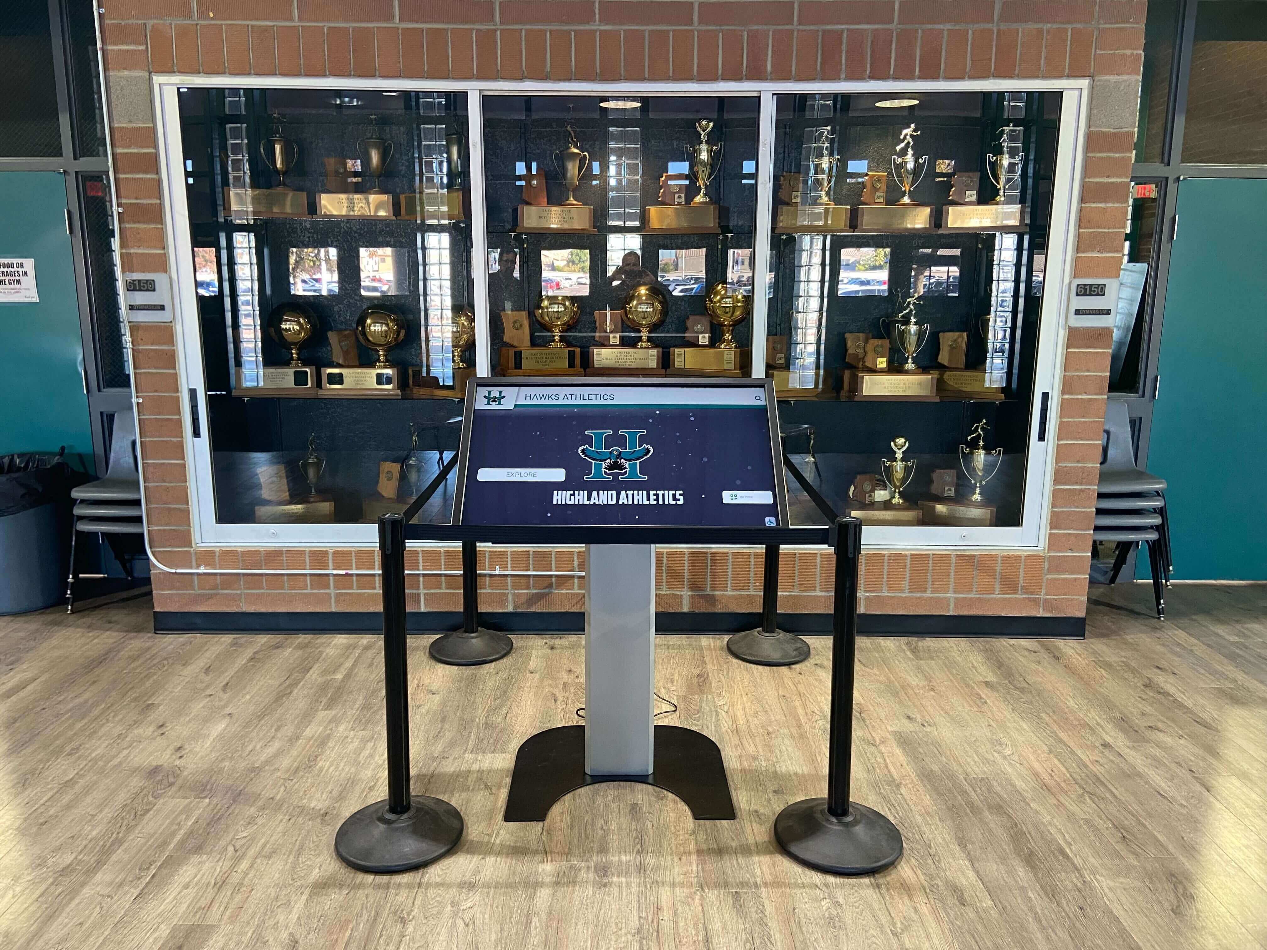
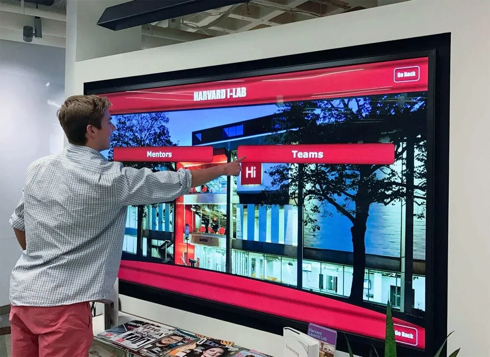
Integrated kiosk enclosures often house the HDBaseT receiver and the display together—checking the receiver's link LEDs is easier when they are accessible inside the enclosure rather than mounted inside a wall
Step 4 — Establish a Direct-Connect HDMI Baseline
Goal: Confirm the media player and display work correctly when the HDBaseT extender is removed from the chain.
- Power off the media player, transmitter, receiver, and display.
- Connect the media player directly to the display with a short HDMI cable (under 6 feet, high-speed rated).
- Power on the display, then the media player.
- Observe whether the recognition content appears. If it does, the source player and display are functioning correctly—the fault is in the HDBaseT extender chain. Proceed to Step 6.
- If video does not appear even on direct connect, the problem is between the player and the display regardless of the extender. Check the player’s HDMI output settings, the HDMI cable, and the display’s input selection before returning to the HDBaseT chain.
This step is the single most important diagnostic in the checklist. Schools that skip it and immediately replace the extender set sometimes discover afterward that the original fault was a failed media player HDMI port—an expensive mistake when the extender hardware was not the problem.
Step 5 — Power-Cycle in Correct Sequence
Goal: Ensure devices complete HDBaseT link training in the correct order. HDBaseT devices must negotiate the link before the source begins sending content.
- Power off all devices: media player, transmitter, receiver, and display.
- Power on the display first and allow it to reach its idle state (30 seconds).
- Power on the HDBaseT receiver next.
- Power on the HDBaseT transmitter.
- Power on the media player last.
- Wait 60 seconds for the full HDBaseT link training and HDMI handshake to complete before evaluating whether video appears.
If video appears after following this sequence but had not appeared before, configure any control system macros, power-scheduling software, or smart power strips to enforce this startup order. An out-of-order power sequence is among the most common causes of HDBaseT black screens reported as “random” failures—they are reproducible once the sequence dependency is understood.
Step 6 — Verify PoHDBaseT Power Delivery
Goal: Confirm the HDBaseT receiver is receiving adequate power when it is powered by the transmitter (Power over HDBaseT) rather than a local power supply.
Many HDBaseT installations power the receiver remotely through the HDBaseT cable itself—the transmitter acts as the power source, eliminating the need for a local outlet at the display location. This is convenient but creates a failure mode: if the power budget is insufficient or the cable resistance is too high, the receiver operates in a degraded or unstable state.
- Identify whether your receiver uses a local power supply (has its own wall adapter) or is powered over HDBaseT. Check the receiver’s specifications sheet.
- If the receiver uses PoHDBaseT: confirm the transmitter’s PoHDBaseT wattage output meets or exceeds the receiver’s power requirement. Common receiver draw is 12–15W; some transmitters are limited to 10W on certain ports.
- Check the transmitter’s PoHDBaseT status LED or web interface. A PoE/power indicator that is off or flashing may indicate the transmitter has exceeded its power budget across multiple PoHDBaseT ports.
- If the run length is near the cable category maximum, the cable resistance is higher—PoHDBaseT voltage drop can push the receiver below its minimum operating voltage. In this case, adding a local power supply to the receiver eliminates the power constraint even if you keep the HDBaseT signal path unchanged.
- If the transmitter is also serving RS-232 or IR control over the same HDBaseT link, that additional channel increases power draw. Verify the total system power budget in the transmitter’s specifications.
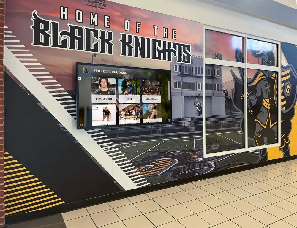
Recognition programs that run athletic record boards and achievement displays across multiple hallways often install multiple HDBaseT links from a central rack—verify each transmitter’s aggregate PoHDBaseT budget, not just the individual port rating.
Step 7 — Check HDBaseT Link Profile
Goal: Confirm the link is training at the expected HDBaseT profile rather than falling back to a reduced mode.
HDBaseT defines multiple operating profiles that trade bandwidth for distance. A link that trains at a lower profile than expected will work for video but drop Ethernet or control channels—or may not carry 4K bandwidth even though the hardware is 4K-capable.
| HDBaseT Profile | Bandwidth | Max Range | Includes |
|---|---|---|---|
| HDBaseT Class A (5Play) | 10.2 Gbps | 100 m on Cat6 | Video, audio, Ethernet, control, power |
| HDBaseT Slim | 10.2 Gbps | 70 m on Cat6 | Video and audio only |
| HDBaseT 2.0 Class A | 18 Gbps | 100 m on Cat6A | 4K HDR, audio, Ethernet, control, power |
| Long Reach (LR) mode | Reduced | 150+ m | Reduced bandwidth for extended distance |
- Access the transmitter or receiver’s web interface or control panel (consult the manufacturer’s documentation for the URL or menu path).
- Locate the link status or diagnostic page. Better-quality HDBaseT devices report the currently negotiated link profile and signal level.
- If the link is negotiating at Long Reach (LR) mode but the cable run is within Class A distance, the cable quality may be marginal. Try forcing Class A mode through the device’s settings page—if the link drops, the cable cannot support Class A at this run length and must be replaced or the run shortened.
- If the Ethernet channel over HDBaseT has been lost while video remains active, the link may have fallen to a profile that does not carry Ethernet. This affects cloud-connected recognition platforms whose content sync depends on that HDBaseT Ethernet path.
Step 8 — Check and Update Transmitter and Receiver Firmware
Goal: Eliminate firmware-level HDBaseT compatibility bugs as a cause of link failure.
HDBaseT transmitter and receiver firmware is updated more frequently than most AV staff realize, and updates often address specific link training failures with particular display models or source devices.
- Identify the make, model, and current firmware version of your HDBaseT transmitter and receiver. This information is typically printed on the unit label or available in the web interface.
- Visit the manufacturer’s support site and check whether newer firmware is available. Common HDBaseT extender brands include Extron, Crestron, Kramer, AMX, and Black Box—check the commercial (not consumer) support portal.
- Read the firmware release notes before updating. Confirm the update addresses HDBaseT link issues rather than unrelated features.
- Update the transmitter and receiver as a matched pair. If the manufacturer provides a matching firmware version for TX and RX, install both simultaneously rather than updating one without the other. A firmware version mismatch between transmitter and receiver is itself a common cause of link training failure.
- Back up any configuration from the device’s web interface if the firmware update tool warns settings may be reset.
- After updating, power-cycle in the correct sequence (Step 5) and observe whether the link trains successfully.
For commercial recognition display installations, firmware updates should be logged in the same maintenance record used for the display hardware and software platform. Schools that document display-related maintenance find it easier to demonstrate program continuity to administrators and boards—the same discipline that supports digital hall of fame program longevity applies to the infrastructure supporting it.
Step 9 — Verify EDID Management Settings
Goal: Confirm the HDBaseT extender is handling EDID (Extended Display Identification Data) correctly so the media player outputs a signal compatible with the recognition display.
EDID is the data set a display sends to its source to advertise its supported resolutions, refresh rates, color depths, and audio formats. In a direct HDMI connection, EDID negotiation is automatic. When an HDBaseT extender sits between the player and the display, the extender must relay or manage EDID on behalf of the display.
- Access the transmitter’s EDID management settings (web interface or front-panel menu). Common options are:
- Pass-through: transmitter reads EDID from the display at the far end and passes it to the source. Works well when the link is stable.
- Fixed/stored EDID: transmitter presents a stored EDID profile to the source regardless of what the display reports. Useful when the HDBaseT link is marginal and EDID read-back fails intermittently.
- If the system uses pass-through EDID and the link is marginal, the source player may be receiving a corrupted EDID that causes it to output an incompatible resolution—resulting in a black screen even when the link is technically trained.
- Switch to a stored EDID that matches your display’s native resolution (1920×1080 for 1080p displays, 3840×2160 for 4K) and retest. Many recognition display deployments work more reliably with a stored EDID than with pass-through, because the source gets a consistent signal specification regardless of link conditions.
- Confirm the stored EDID includes the correct color space (typically RGB or YCbCr 4:4:4 for recognition content) and does not advertise HDR profiles the display cannot support.
The EDID issue surfaces frequently in school environments where the recognition display is replaced mid-life with a newer model that has a different EDID profile—the transmitter was configured for the old display and now presents incompatible data to the source.
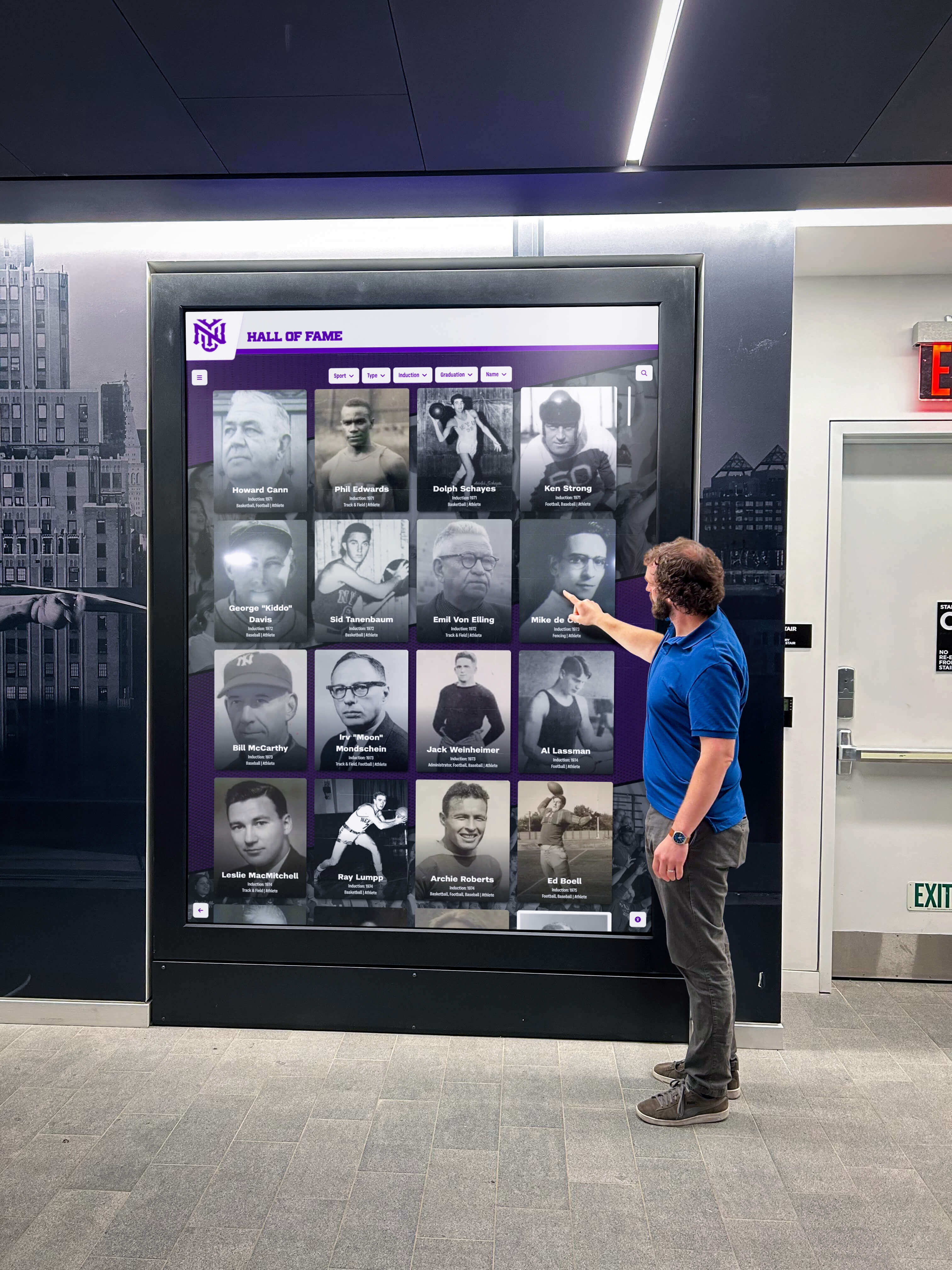
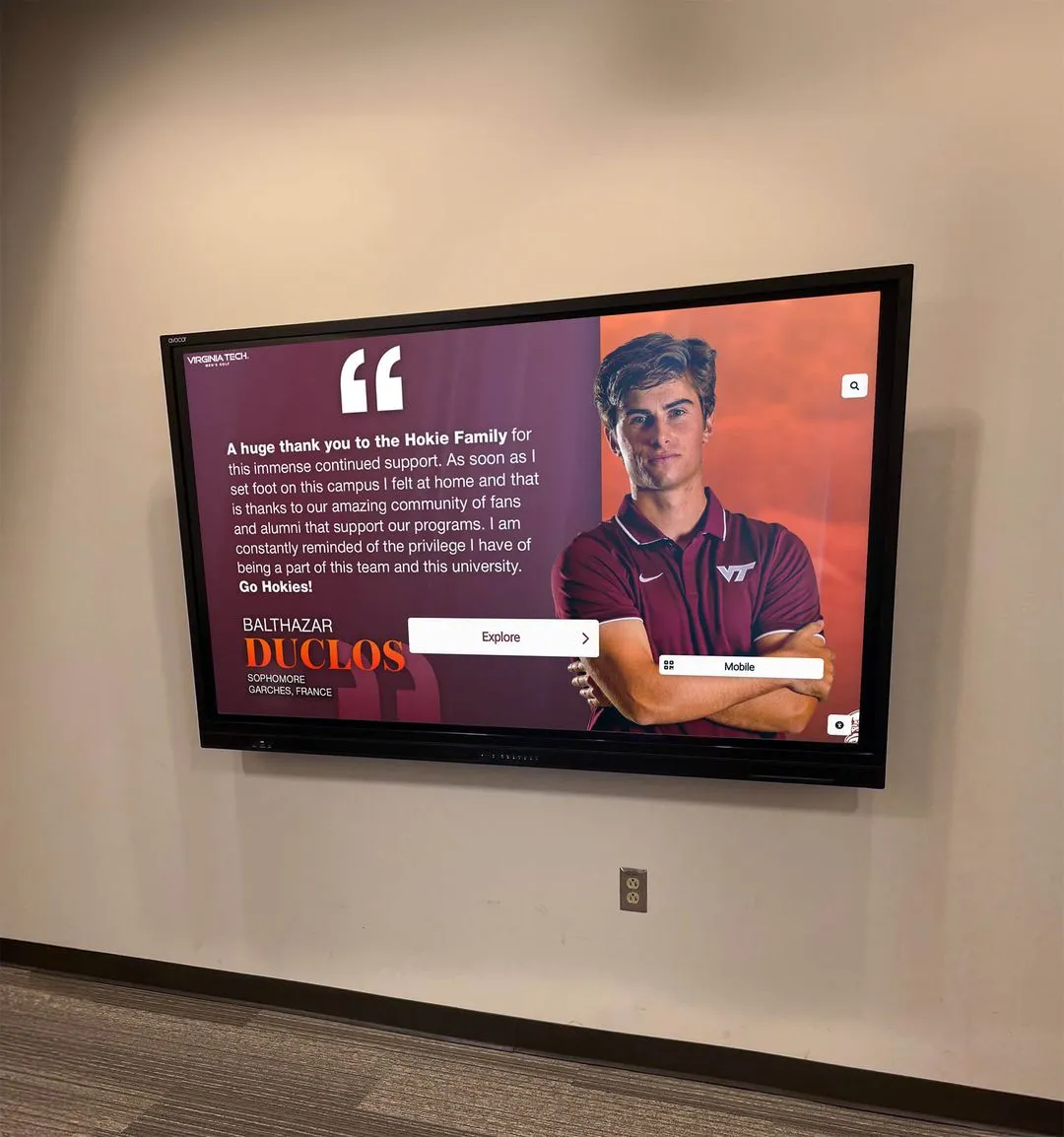
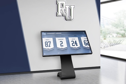
Visitors expect the recognition display to work every time they arrive—EDID mismatches are one of the most commonly overlooked causes of a blank screen that appears correct in all physical checks
Step 10 — Substitute a Known-Good Extender Set
Goal: If all prior steps pass but the fault persists, confirm by hardware substitution whether the transmitter or receiver has failed.
- Borrow a working HDBaseT extender set of the same or compatible model from another location in the building, or request a temporary loan unit from your AV vendor.
- Substitute the borrowed transmitter first (keeping your original receiver), power-cycle correctly, and observe whether the link trains.
- If the link trains with the borrowed transmitter, your original transmitter has likely failed. Replace it.
- If the link still fails with the borrowed transmitter, substitute the receiver with the borrowed receiver and retest.
- If the link trains with the borrowed receiver, your original receiver has failed. Replace it.
- Before ordering replacements, verify the replacement model’s specifications match your cable category, run length, power requirements, and HDCP version—replacing a failed extender with an incompatible model solves one problem and creates another.
Step 11 — Document the Resolution and Prevent Recurrence
Goal: Record the fault, its cause, and the fix so the next event day does not start with the same troubleshooting process.
- Write a one-page AV chain diagram showing the media player, transmitter, Cat cable (with labeled run length and cable category), receiver, and display—with firmware versions noted for TX and RX.
- Note the power-on sequence that works and post it inside the AV rack door or on a laminated card at the transmitter.
- Record the fault type (cable, firmware, EDID, PoHDBaseT) and the fix in a maintenance log. This becomes the first reference when any future failure occurs.
- Set a calendar reminder to check for TX/RX firmware updates annually and after any major display or media player upgrade.
- If the failure was a cable category or run length issue, add a note to the technology refresh plan flagging the cable run for replacement when the display is next upgraded.
Sharing the completed AV chain diagram with the athletic director, booster club technology liaison, and facilities coordinator—not just the IT team—ensures that anyone who sets up the recognition display for an event has the reference they need before calling for support. The same spirit of keeping complete, accessible records that drives academic honors recognition programs applies to the technical documentation that keeps recognition displays running.
Quick-Reference Checklist Summary
Use this condensed version as a laminated card posted inside the AV equipment cabinet.
Before every major event:
- Power on display → receiver → transmitter → media player (in that order)
- Confirm the LINK LED is solid on both TX and RX
- Confirm recognition content is visible at least 30 minutes before guests arrive
If black screen or flickering appears:
- Inspect cable and connectors visually
- Verify cable category and run length
- Check TX and RX link LEDs
- Direct-connect HDMI bypass test (removes extender)
- Power-cycle in correct sequence
- Verify PoHDBaseT power delivery
- Check HDBaseT link profile in device web interface
- Check and update TX and RX firmware (as matched pair)
- Verify and adjust EDID settings
- Substitute known-good extender set
- Escalate to vendor or AV integrator if unresolved
Escalation Table: When to Call a Professional
Some HDBaseT failures are beyond safe DIY resolution. Use this table to decide when to escalate.
| Situation | Recommended Action |
|---|---|
| Run length exceeds cable category maximum | Engage a low-voltage cabling contractor to replace the cable run |
| Firmware update requires hardware disassembly | Contact the manufacturer’s commercial technical support line |
| HDBaseT extender serves shared AV infrastructure (auditorium, gym, broadcast) | Involve a licensed AV integrator before changing shared settings |
| PoHDBaseT upgrade requires new transmitter with higher power budget | Request a formal AV infrastructure assessment before purchasing |
| Link failure persists after all steps pass | Engage the recognition display vendor; platform-level output settings may need adjustment |
| Cable must be re-pulled through existing conduit | Hire a licensed low-voltage contractor; most jurisdictions require licensing for in-conduit rework |
| Multiple extender failures across a campus | Commission an AV infrastructure assessment to identify systemic cable plant or power budget issues |
Schools expanding interactive kiosk and recognition display programs across multiple buildings should involve a licensed AV integrator at the design stage rather than after multiple point failures. An integrator can specify cable categories, run lengths, and PoHDBaseT budgets as a coordinated system rather than on a display-by-display basis.
Design Choices That Reduce HDBaseT Failures Long-Term
Prevention is more efficient than event-day troubleshooting. Schools planning new recognition display installations or upgrades can build HDBaseT infrastructure that reduces future failure risk from the start.
Specify Cat6A for all new runs. Even if today’s content is 1080p, Cat6A supports 4K HDBaseT 2.0 at full 100-meter distance and provides headroom for future upgrades without re-pulling cable. The marginal cost difference between Cat6 and Cat6A is small relative to the labor cost of a future cable replacement.
Use professional-grade, not consumer-grade, extenders. Consumer HDMI-over-Cat extenders from electronics retailers are not rated for continuous operation and frequently lack accurate PoHDBaseT management and EDID handling. Commercial HDBaseT hardware from Extron, Crestron, Kramer, AMX, and Black Box carries explicit compliance certification and typically includes web management interfaces for remote diagnostics.
Keep the signal chain short where possible. Each patch panel connection, connector, and cable segment adds insertion loss. Where recognition display locations are close to an equipment room, a short direct Cat run is always more reliable than a long run with multiple patch points.
Install a local power supply at the receiver even if PoHDBaseT is available. Local power eliminates one failure variable—PoHDBaseT voltage drop over long runs is a recurring cause of intermittent failures that are difficult to diagnose. The outlet cost is minimal compared to the troubleshooting time a PoHDBaseT failure can generate.
Document the full AV chain at installation. The installers who pull cable and configure extenders know where every run goes. That knowledge leaves with them. A one-page AV chain diagram with run lengths, cable categories, firmware versions, and power-on sequences—created at installation and stored in the IT documentation system—ensures any future team member can diagnose and resolve failures without reconstructing the entire installation history. Schools building alumni recognition event programs that rely on recognition displays for inductee presentations cannot afford an AV failure discovered the night of the event.
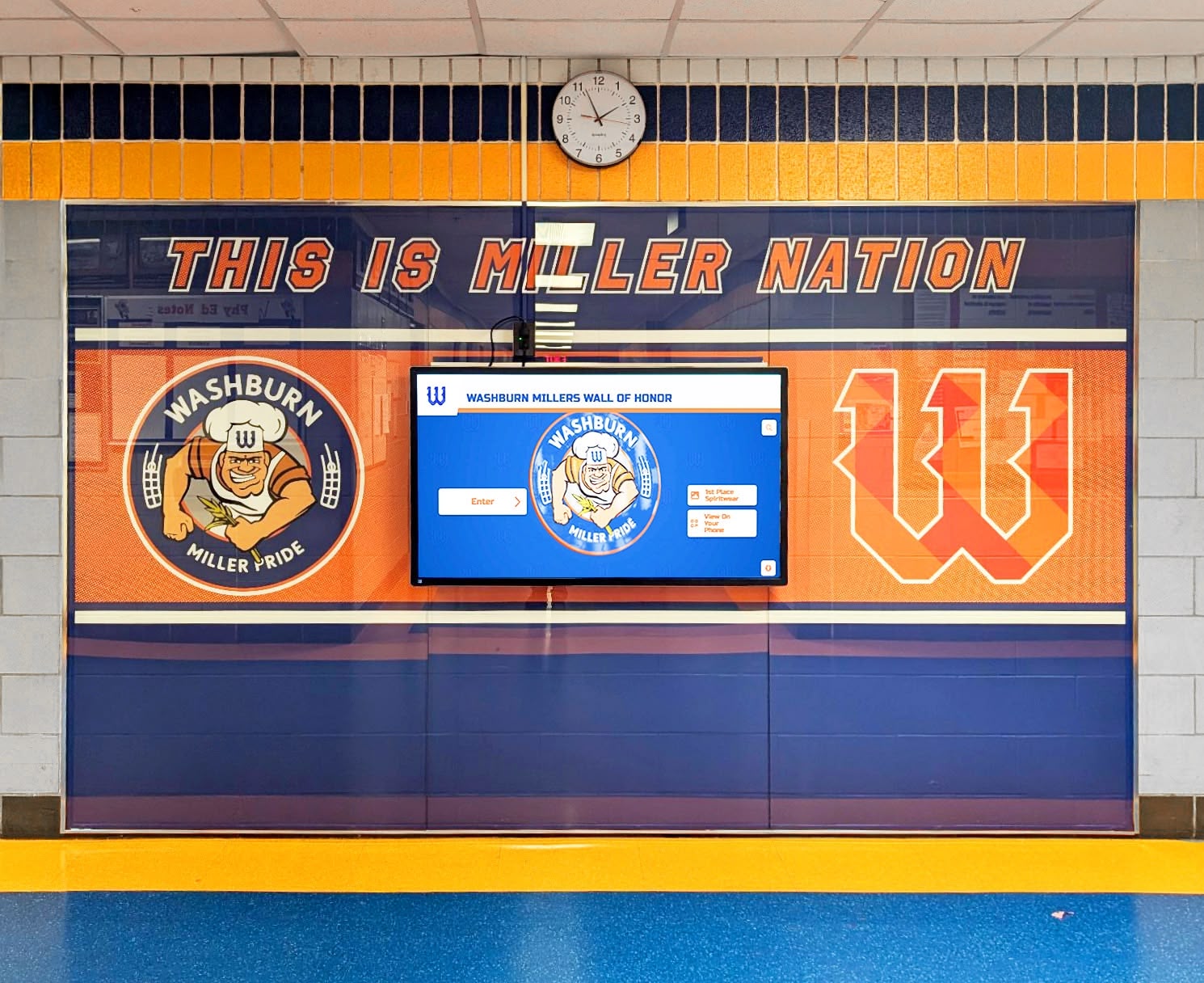
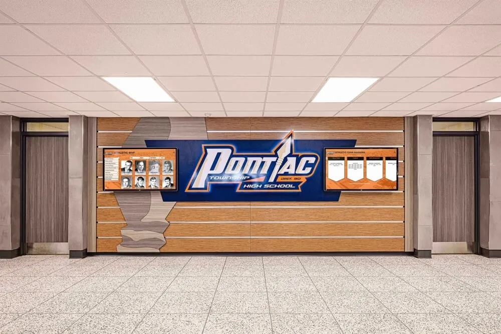
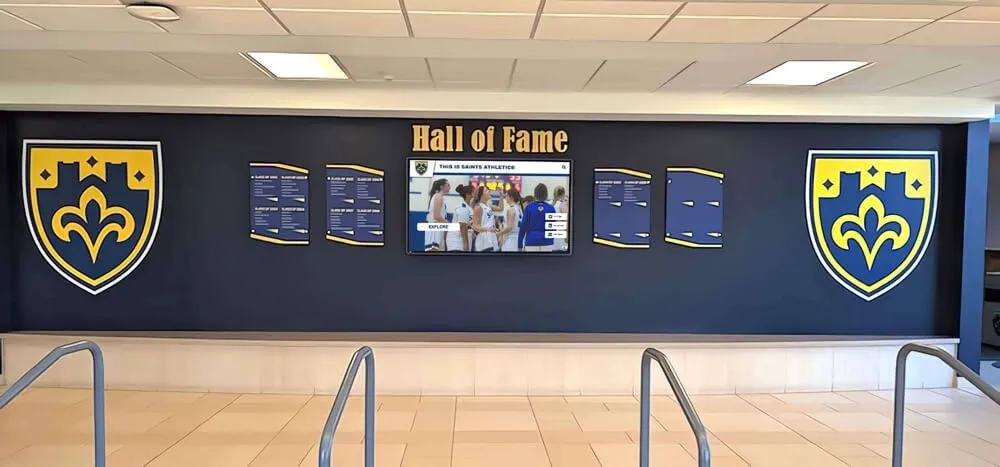
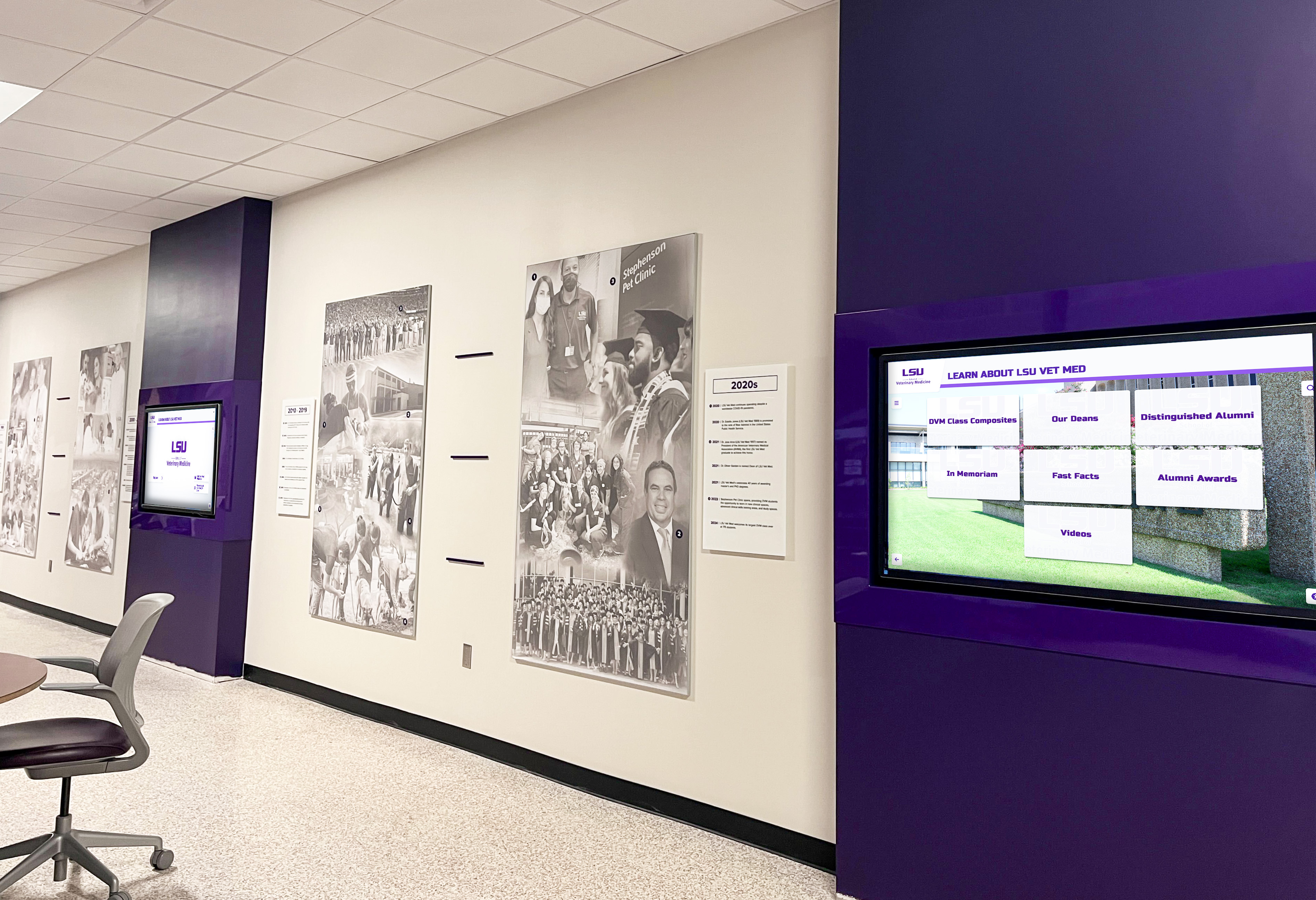
Every recognition display in a school hallway has an HDBaseT infrastructure behind it—documenting that infrastructure at installation makes future maintenance straightforward for any staff member who inherits the system
Special Considerations for School AV Environments
Shared Infrastructure and Third-Party Access
Many schools route recognition display HDBaseT transmitters through the same equipment rack as classroom AV, auditorium video, or broadcast systems. Before adjusting shared transmitters, switchers, or rack power units, confirm with the AV coordinator or IT director that changes will not affect other systems. In multi-display racks where PoHDBaseT budgets are shared across several transmitters, adding a high-draw transmitter to a full rack can cause other displays to lose power—a non-obvious failure that appears to be a hardware fault on the affected displays.
Athletic Banquets, Induction Nights, and Homecoming Events
Recognition events are exactly when HDBaseT failures cause the most disruption—and exactly when technical staff may not be on campus. Building a simple pre-event verification procedure (power on in sequence, confirm LINK LEDs, confirm content visible) into the event setup checklist—and assigning it to a staff member, not an outside volunteer—prevents most event-day failures. Schools that honor athletes at seasonal banquets and golf award programs and other sport-specific events should verify their recognition display AV chain the day before, not the hour before.
Renovation and Construction Periods
School renovation projects frequently damage or disrupt in-wall HDBaseT cable runs. A display that worked before a nearby construction project may fail afterward because vibration loosened a connector, drilling compromised a conduit run, or a contractor inadvertently cut a cable. When a recognition display fails in proximity to recent construction, inspect the cable run for physical damage before running any electronic diagnostics.
After-Hours IT Access
Recognition display AV failures do not always happen during school hours when IT staff are on campus. Providing the athletic director, facilities supervisor, and booster organization technology contact with a laminated copy of the power-on sequence and basic LED troubleshooting steps—along with the recognition platform vendor’s support number—gives non-technical staff a first-response capability that handles a majority of HDBaseT failures without requiring an IT call-in. For programs maintaining athletic archives and historical records on their recognition displays, continuity of display operation is part of the responsibility of preserving those records accessibly.
Frequently Asked Questions
Can we use Cat5e for a new HDBaseT recognition display installation?
Cat5e supports HDBaseT at 1080p up to approximately 70 meters, which is adequate for many school runs. However, if there is any possibility that the display will be upgraded to 4K in the future, or if the run length is over 60 meters, specifying Cat6 or Cat6A at installation eliminates the need to re-pull cable later. The incremental material cost of Cat6A versus Cat5e is small; the labor cost of re-pulling cable through conduit is significant.
What is the maximum cable run for 4K content over HDBaseT?
At HDBaseT 2.0 Class A, the maximum run for 4K (18 Gbps bandwidth) is 100 meters on Cat6A. On Cat6, the practical limit for 4K is typically 70 meters, though the exact figure depends on the transmitter and receiver manufacturers’ specifications. At these distances, cable termination quality becomes critical—a poorly crimped connector at either end can reduce effective distance by 15–20 meters.
Should we use Cat7 cable for HDBaseT recognition display runs?
Cat7 is a shielded cable (S/FTP) and requires shielded connectors and HDBaseT hardware designed for shielded cable. Using Cat7 with unshielded (standard) HDBaseT extenders typically produces worse results than Cat6A because improper grounding of the shield introduces noise rather than reducing it. Unless your HDBaseT hardware explicitly supports shielded Cat7 cabling, Cat6A is the correct choice.
Do HDBaseT extenders affect HDCP authentication for recognition displays?
Yes. HDBaseT extenders that are HDCP-compliant pass the HDCP authentication handshake between the media player and the display. Extenders that do not explicitly state HDCP compliance may block the handshake, producing a black screen that looks like an HDBaseT signal failure but is actually an HDCP failure. When purchasing extender hardware for recognition displays that run DRM-protected video content (streaming platforms, HDCP-protected Blu-ray), verify the extender’s HDCP version matches your content requirements (HDCP 1.4 for 1080p content, HDCP 2.2 for 4K premium content).
Why does our recognition display work in the morning but fail after the building warms up?
Thermal expansion can cause marginal connectors to lose contact and degrade Cat cable electrical performance. In facilities with large temperature swings between overnight and midday, a connection that is borderline at cool temperatures becomes an open or high-resistance connection at operating temperature. If the display reliably fails at a consistent time of day during warm months, inspect all connectors in the HDBaseT path and replace any that show any looseness or corrosion. Replacing a borderline Cat cable run with a higher-category cable also increases the margin against thermal effects.
Does wireless HDBaseT exist as an alternative for renovation situations?
Wireless HDMI extender systems exist that operate over 60 GHz or 5 GHz bands, but none use the HDBaseT standard—these are different technologies with shorter ranges, higher susceptibility to interference, and generally lower reliability for continuous school-hours operation. For permanent recognition display installations, wired HDBaseT over Cat cable remains the correct approach. For temporary event setups where a recognition display must be positioned where no cable infrastructure exists, short-range wireless HDMI can serve as a temporary solution, but the setup should not be treated as a permanent installation.
Recognition displays celebrate the achievements—the letterman jacket milestones, the state championship seasons, the academic honors—that define a school’s culture across generations. Understanding what those achievements mean to students and alumni is the program side of recognition; keeping the display reliable enough to show those achievements every day is the infrastructure side. A documented HDBaseT link integrity test, run at installation and revisited annually, ensures the technical foundation is as solid as the recognition program built on top of it.
See how Rocket Alumni Solutions recognition displays are designed for reliable school AV environments—with deployment documentation, hardware recommendations, and support built for AV and IT teams who maintain real buildings.