

School IT teams that have built redundant uplinks between their access and distribution switches using link aggregation—also known as a LAG, port channel, or EtherChannel—gain meaningful protection against a single cable or transceiver failure taking down an entire network segment. That same protection must be validated before a recognition display, athletic hall-of-fame kiosk, or digital lobby screen goes live on the aggregated segment, because an untested LAG can mask configuration problems that only surface when a member link actually fails during a scheduled awards presentation or live content update.
Link aggregation bundles two or more physical links into a single logical interface. When it is working correctly and one member link fails, the switch redistributes traffic to the surviving links and the recognition display continues operating without interruption. When the LAG is misconfigured—mismatched hashing algorithms, incorrect LACP modes, or unsupported hardware combinations—a single member failure causes the entire logical interface to drop rather than gracefully shedding the failed port. Schools that have not run a structured school recognition display link aggregation test before deployment cannot distinguish between a working redundant uplink and one that only appears to be redundant.
This guide gives school network administrators, technology coordinators, and facilities IT staff a structured procedure for testing link aggregation on the switch uplinks that carry recognition display traffic. It covers LACP negotiation verification, member-link state validation, traffic hashing confirmation for media streams, controlled member-failure simulation, failover timing measurement, and re-convergence testing—with numbered steps and troubleshooting guidance for each failure mode.
Quick answer: A switch uplink LAG passes the school recognition display link aggregation test when four conditions are met simultaneously. First, LACP negotiation must be complete on all configured member ports, with each port showing an active or passive state and an established LACP partner. Second, all member links must be in the forwarding state with no ports suspended or in standby due to speed, duplex, or configuration mismatches. Third, recognition display traffic—including the content update stream and management traffic—must be hashing across the LAG to at least one member link, confirmed by per-member counters increasing. Fourth, a simulated member-link failure must leave the logical interface operational with traffic migrating to the surviving members and the recognition display maintaining its connection to the content management platform within the vendor’s documented failover window.

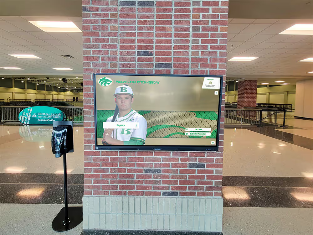
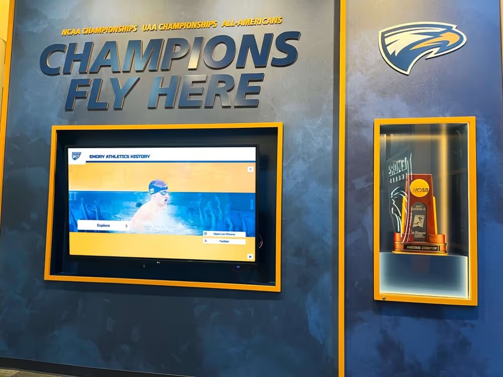
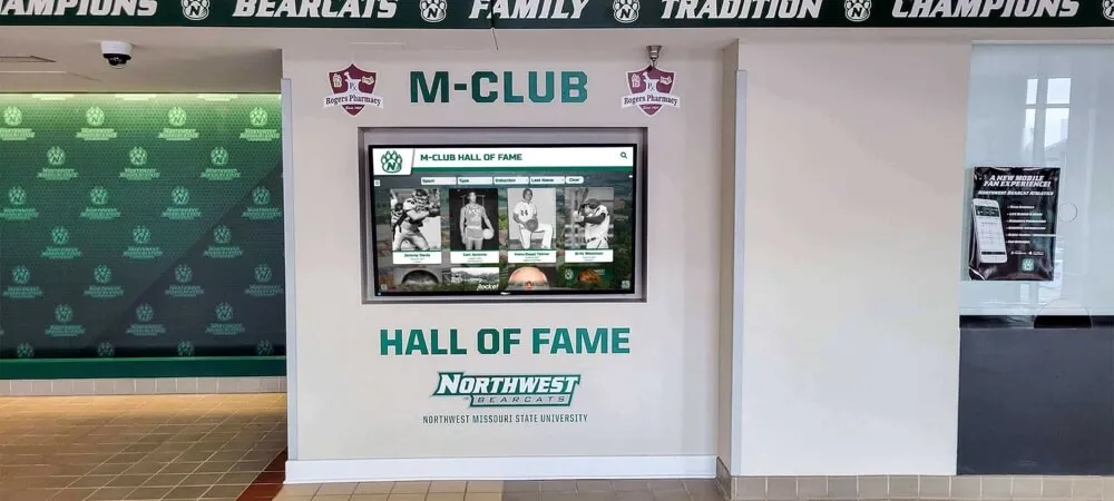
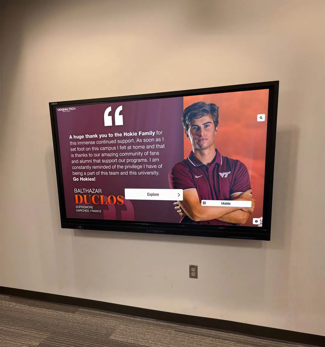
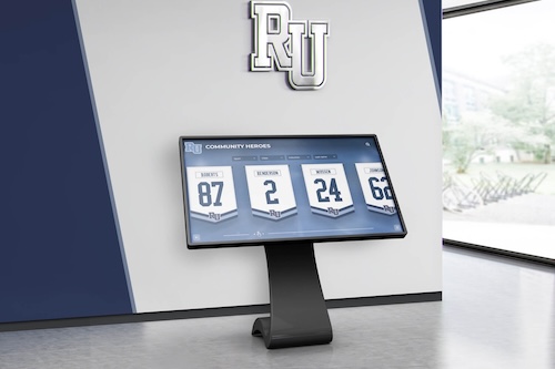
Digital recognition displays in school hallways depend on the uplink from the access switch to the distribution layer — an untested link aggregation group offers only the appearance of redundancy
What Link Aggregation Is and Why It Matters for School Recognition Displays
Link Aggregation (LAG), standardized as IEEE 802.1AX (originally IEEE 802.3ad), combines multiple physical Ethernet links between two directly connected switches into a single logical interface. The switch presents this logical interface to the rest of the network as one connection with a combined bandwidth equal to the sum of the member links. LACP—the Link Aggregation Control Protocol—is the negotiation mechanism that lets both sides of the link agree on which ports participate in the aggregate, what the hashing policy is, and how member-link failures are handled.
In school network deployments, link aggregation appears most commonly on the uplink between an access-layer switch in a hallway IDF closet and the distribution or core switch in the main MDF. A school that deploys a pair of recognition displays in an athletic lobby or trophy corridor routes all display traffic—content updates, management heartbeats, DNS queries, and cloud platform connections—through that access-layer uplink. A single 1GbE uplink is a single point of failure. A LAG built from two 1GbE cables (or two 10GbE SFP+ cables) provides both additional bandwidth and the redundancy needed to survive a cable pull, transceiver failure, or port hardware issue without the display going offline.
The key distinction IT teams must understand is that link aggregation redundancy is not the same as automatic failover without testing. A LAG that negotiates correctly under normal conditions can still fail completely if a member link is lost and the LAG configuration has errors that only the failure condition exposes. Common examples include:
- Both switch ports on one side of the link configured for LACP passive mode (neither side initiates negotiation, so the LAG never recovers after a re-plug)
- Mismatched member-link speeds causing one port to suspend while appearing to be part of the aggregate in status output
- A hashing algorithm that maps all recognition display traffic flows to one member link, so a failure of that specific link causes a display outage even though another member remains active
- Minimum-links LAG configuration set to the total member count rather than one less than total, so any single failure collapses the aggregate
Running a structured test before the recognition system goes live—and after any switch or cabling change—is the only way to confirm the LAG delivers actual redundancy rather than theoretical redundancy.
Link Aggregation Terminology Reference
| Term | Meaning | Notes |
|---|---|---|
| LAG | Link Aggregation Group | Generic term; used in IEEE 802.1AX and HP/Aruba documentation |
| Port Channel | Logical interface representing the LAG | Cisco IOS/IOS-XE terminology |
| EtherChannel | Cisco proprietary name for its LAG implementation | Supports both LACP and PAgP |
| Bundle / Bundle-Ether | Logical LAG interface on Cisco IOS-XR and Juniper EX | Vendor-specific naming |
| LACP | Link Aggregation Control Protocol | IEEE 802.1AX control plane; preferred over PAgP or static LAG |
| Member link | Individual physical port participating in the LAG | Also called “member port” or “physical member” |
| Active LACP mode | Port actively sends LACP PDUs to initiate negotiation | At least one side must be active |
| Passive LACP mode | Port responds to LACP PDUs but does not initiate | Cannot connect passive-to-passive |
| Hashing / load balancing | Method for distributing traffic across member links | Source/destination IP, MAC, or port; vendor-specific options |
| Minimum links | Minimum active members before LAG is declared down | Should be set below total member count for redundancy |
Why School Recognition Displays Stress LAG Configurations Differently Than Generic Traffic
Recognition displays are not generic web clients. Their traffic patterns differ from the typical mix of HTTPS page loads and file transfers that switch uplinks usually carry:
Scheduled content bursts. Recognition platforms push updated athlete profiles, award graphics, and video highlights to displays on a schedule—often every few minutes during periods when content is actively managed. These bursts create short-lived high-bandwidth flows. If all burst traffic hashes to a single LAG member, that member link operates at or near capacity while others sit idle. A failure during a burst has a disproportionate effect on the user experience because the display’s content update is in progress.
Long-lived management connections. The recognition platform maintains a persistent TCP connection between the display host and the cloud management endpoint. Unlike HTTP requests that open and close quickly, this connection can persist for hours or days. When a LAG member fails and traffic re-hashes, a long-lived TCP connection may need to re-establish if its session state is not preserved—causing the display to show a stale offline status on the management dashboard until the connection recovers.
Low tolerance for visible interruption. A recognition display in a school lobby is in continuous public view. A few seconds of black screen or frozen content during a LAG failover is visible to students, families, and visiting athletic programs in a way that a brief email server blip is not. Schools planning athletic recognition events and sports banquets where the digital display is part of the ceremony have zero tolerance for visible uplink failures during those events.
Multicast or broadcast media in some deployments. Schools that distribute live event video or streaming highlights to lobby displays may use multicast traffic across the same uplink. Multicast traffic hashing across a LAG has specific requirements that differ from unicast hashing and can expose LAG configuration errors that unicast-only testing would miss.
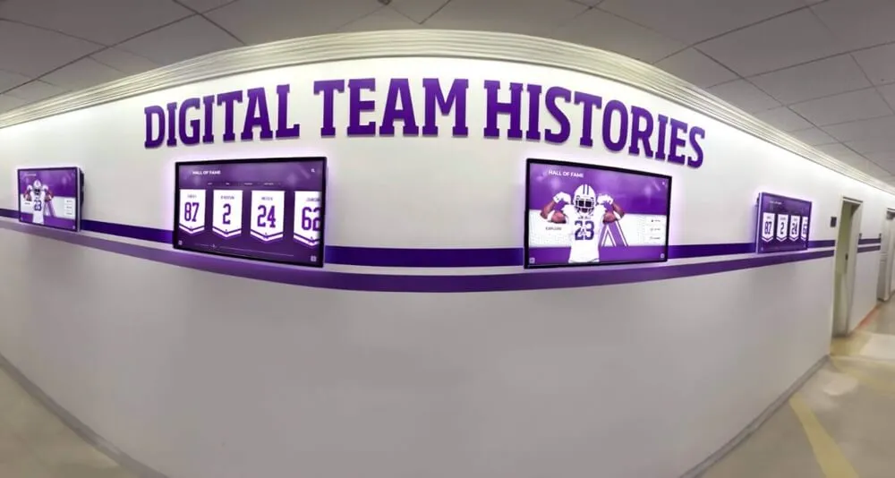
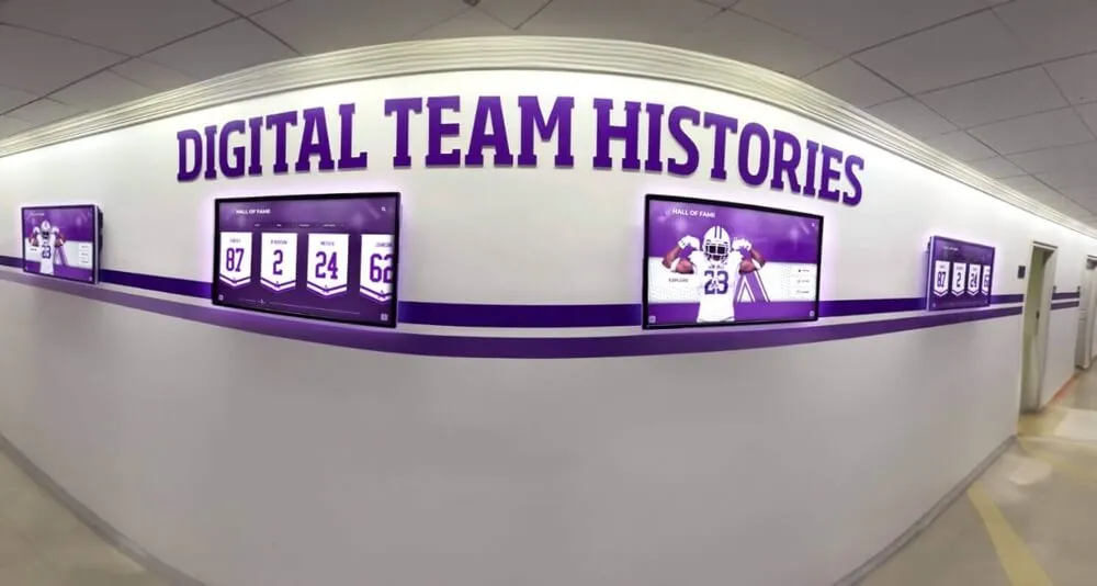
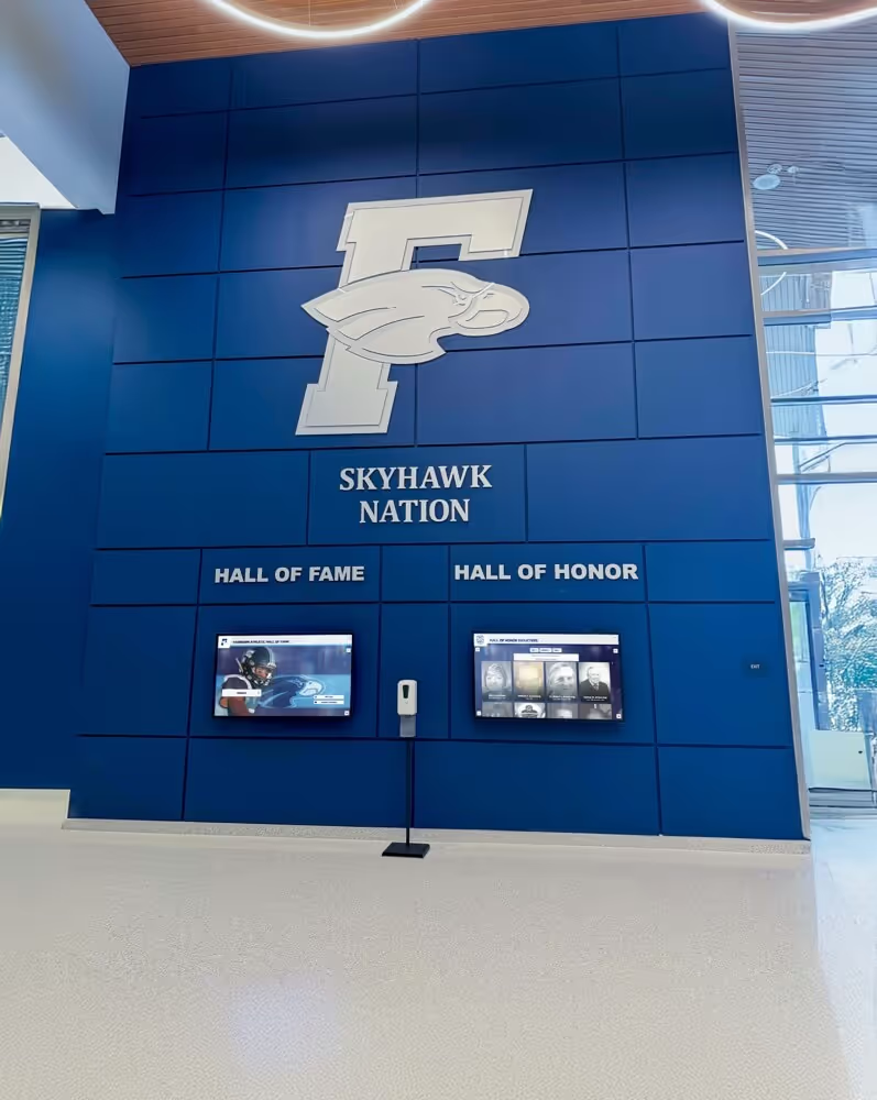
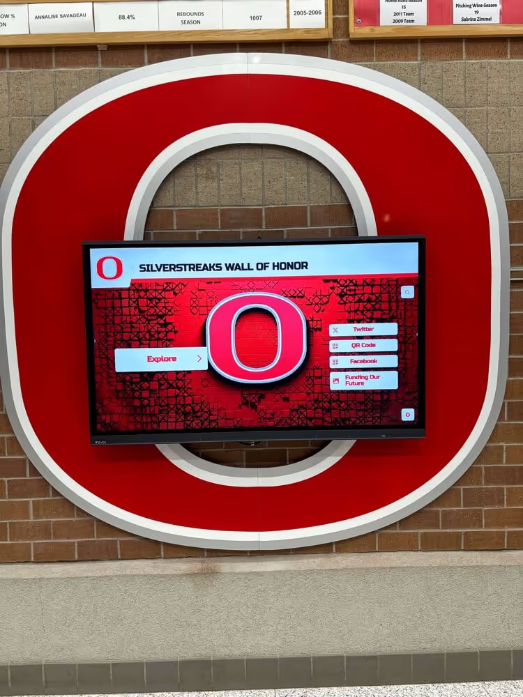
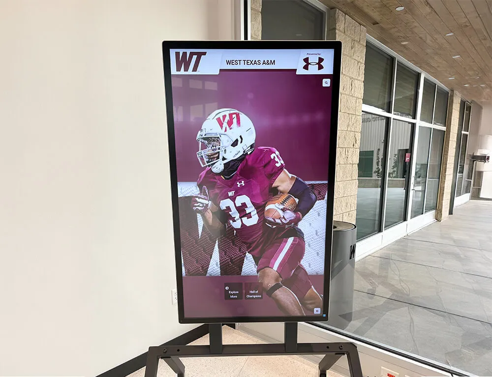
Content-rich athletic team history displays place scheduled traffic bursts on uplinks — a LAG test that includes a simulated member failure during an active content update confirms real-world redundancy
Pre-Test Preparation Checklist
Before running the validation steps, collect the following information. The test procedure references these values in switch CLI commands, so having them documented before starting eliminates the need to pause mid-test.
| Information | Description | How to Collect |
|---|---|---|
| LAG interface identifier | Port-channel number, bundle ID, or LAG name on both switches | Check switch running configuration: show running-config interface port-channel <n> (Cisco) or show lagg (HP/Aruba) |
| Member port identifiers | Physical interface names for each member link (e.g., GigabitEthernet1/0/1, GigabitEthernet1/0/2) | show interfaces port-channel <n> etherchannel (Cisco) or show lacp <n> internal |
| LACP mode on each side | Active or passive on the access-layer switch and the distribution switch | show lacp <n> internal and show lacp <n> neighbor (Cisco) |
| Hashing algorithm | Method used to distribute traffic across member links | show etherchannel load-balance (Cisco) or equivalent |
| Minimum-links setting | Number of active members required before LAG is declared down | show running-config interface port-channel <n> — look for port-channel min-links |
| Display IP and MAC address | Used to generate test traffic and verify hashing | ipconfig /all on the display host; check ARP table |
| Content platform endpoint IP | Destination for recognition platform traffic; used to verify correct member link carries display flows | Check display host connections with netstat -ano |
| Switch management access | SSH or console access to both the access switch and distribution switch | Confirm with network administrator before starting |
| Scheduled content window | When the recognition platform pushes updates to this display | Check platform dashboard or consult vendor documentation |
Collect all values before proceeding. Identifying which member link carries the display’s traffic flow—before simulating a failure—is the most important pre-test step and is covered in detail in the traffic hashing verification section below.
Planning a recognition display deployment on a school network with aggregated uplinks or other resiliency requirements? Rocket Alumni Solutions works with school IT teams on network compatibility documentation and can coordinate deployment timing around your maintenance windows.
See how Rocket Alumni Solutions supports school network deployment
Step 1: Verify LACP Negotiation on Both Switches
A LAG that is negotiated via LACP provides dynamic member management. A static LAG (also called a manual or on-mode LAG) does not exchange LACP PDUs and provides no protocol-level recovery mechanism when a member fails. For recognition display uplinks, LACP is strongly preferred because it detects unidirectional link failures that a static LAG would not catch.
Step 1a: Confirm LACP is enabled on the access switch
On the access-layer switch, run the following commands and confirm the outputs described:
show lacp <lag-number> internal
Expected output fields:
- State:
A(Active) orP(Passive) — at least one side of the link must showA - LACP port: port number assigned; any nonzero value confirms LACP is running
- NTT:
0(Neighbor Timeout Timer) indicates negotiation is stable;1indicates the port is actively transmitting LACP PDUs and waiting for a response
show etherchannel <lag-number> summary
Expected output:
- Port-channel interface status:
SU(Layer 2 Up) orRU(Layer 3 Up) - Member ports: each physical member should show
P(bundled in port-channel) — notI(individual/not bundled),s(suspended), orD(down)
If any member shows s (suspended), the most common causes are a speed or duplex mismatch between the two ends of that cable, a misconfiguration where one end is set to on mode (static) and the other to active LACP mode, or a hardware fault on the SFP transceiver or copper port.
Step 1b: Confirm LACP negotiation from the distribution switch
On the distribution switch, run:
show lacp <lag-number> neighbor
This output shows the partner system ID, partner port, and operational key from the access switch’s perspective. Confirm that:
- The system ID matches the access-layer switch’s MAC address prefix
- The operational key matches on both ends (mismatched keys prevent bundle formation)
- All expected member ports appear as LACP neighbors
Step 1c: Check LACP system priority and port priority
show lacp sys-id
In environments where more than the maximum active member count of physical ports are configured (uncommon in school two-switch uplinks but possible if four cables are run and the switches only support two active members), LACP uses port priority to select which members are active and which enter hot-standby. Confirm that the priority assignments match your design intent.
Step 2: Verify All Member Links Are Forwarding
With LACP negotiation confirmed, verify that every configured member link is actually carrying traffic—not in standby, suspended, or error-disabled state.
Step 2a: Check per-member interface counters
show interfaces GigabitEthernet1/0/1 counters
show interfaces GigabitEthernet1/0/2 counters
Run these commands twice with a 30-second interval. Both member interfaces should show increasing input and output packet counts between the two samples. If one member shows static counters while the other increases, that member is bundled in the LAG configuration but is not actually receiving traffic—which means the LAG is not load balancing correctly or that member has a physical problem.
Step 2b: Verify no CRC or input errors are accumulating
show interfaces GigabitEthernet1/0/1
show interfaces GigabitEthernet1/0/2
Look at the input errors, CRC, and giants/runts counters. A small number of CRC errors (in the low double digits) on a production interface that has been running for months may be historical. CRC errors that are actively incrementing between two CLI samples indicate a physical layer problem on that member cable or transceiver—a failing physical member that passes link negotiation but degrades LAG performance.
Recognition displays that are honoring youth athletes and displaying award records depend on reliable content delivery paths. Active CRC errors on a LAG member represent a latent failure that will likely cause a complete member loss at an unpredictable time—replace the cable or transceiver before proceeding with the LAG test.
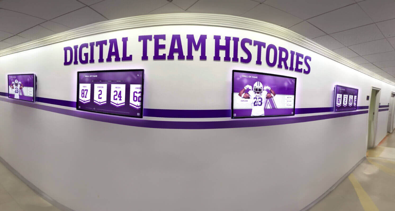
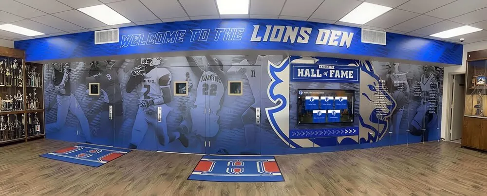
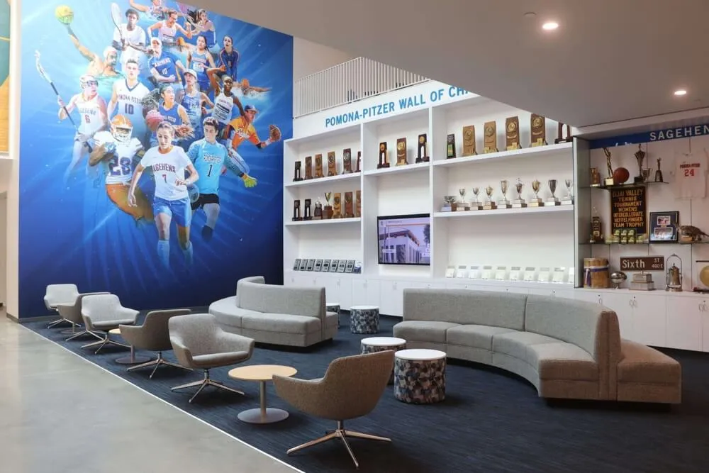
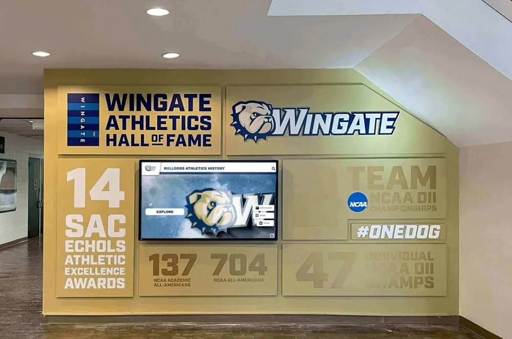
When multiple recognition displays share the same aggregated uplink, per-member traffic counters confirm that load balancing is distributing content update flows across all available member links
Step 3: Confirm Traffic Hashing for Recognition Display Flows
Before simulating a member failure, identify which physical member link currently carries the recognition display’s management and content traffic. This step is essential because the failure test in Step 4 simulates removing the specific member link that carries the display’s flow—if you remove the wrong member, the test does not validate the scenario that would cause a display outage.
Step 3a: Determine the hashing algorithm
show etherchannel load-balance
Common hashing options and their implications for recognition display traffic:
| Hash Method | Based On | Implication for Display Traffic |
|---|---|---|
| src-mac | Source MAC address only | All traffic from the display hashes to one member; useful baseline |
| dst-mac | Destination MAC address | Distribution depends on destination — display reaching multiple endpoints may spread across members |
| src-dst-mac | Source and destination MAC XOR | Good distribution for unicast flows to multiple destinations |
| src-ip | Source IP only | All display traffic hashes to one member if display has one IP |
| dst-ip | Destination IP | Traffic spreads if display reaches multiple destination IPs |
| src-dst-ip | Source and destination IP XOR | Most common production setting; spreads flows effectively |
| src-dst-ip-l4port | 4-tuple hash | Best distribution; requires Layer 4 support in switch hardware |
For a recognition display with a single source IP communicating primarily with one content platform endpoint IP, a src-dst-ip hash will typically assign all display traffic to one specific member link. That is expected behavior—record which member link.
Step 3b: Use the hash calculation utility (Cisco)
Cisco IOS provides a built-in tool to predict which member link a specific flow will use:
test etherchannel load-balance interface port-channel <n> ip <display-IP> <platform-endpoint-IP>
The output identifies the physical member port that will carry traffic matching that source/destination IP pair. This is the member you will simulate failing in Step 4.
Step 3c: Verify with live counters
Confirm the prediction by watching per-member counters while the display is actively communicating:
show interfaces port-channel <n> etherchannel
The per-member traffic distribution in the output should show the predicted member accumulating bytes matching the display’s traffic volume.
Step 4: Simulate a Member-Link Failure and Measure Failover
This is the critical test. With the hashing member confirmed, simulate a physical member failure and measure how the LAG and recognition display respond.
Step 4a: Notify the appropriate stakeholders
Before pulling a cable or administratively shutting down a port, confirm that:
- The recognition display is in its normal operating state with active content (not already in an error condition)
- The school is not in the middle of a scheduled awards event or presentation where the display is in active use
- Another IT team member is physically at the display to observe any visual interruption
- You have switch management access and can restore the member link quickly if needed
Step 4b: Time the baseline content update cycle
On the recognition platform dashboard, note the time of the display’s most recent successful check-in. Open a persistent ping from a monitoring workstation on the same VLAN to the display’s IP address and record the baseline round-trip time:
ping <display-IP> -t
This ping stream will show the exact moment of any connectivity interruption and how long recovery takes.
Step 4c: Administratively shut the identified member port
Rather than physically pulling a cable (which can cause a brief link flap before the port goes down), use the CLI to gracefully shut the member port. This produces a clean test:
interface GigabitEthernet1/0/1
shutdown
Record the exact time of the shutdown command.
Step 4d: Observe the LAG response on the switch
Immediately after the shutdown:
show etherchannel <n> summary
Expected output: The shut member shows D (down) and is removed from the bundle. The remaining member shows P (bundled). The port-channel interface itself should remain SU or RU—not go down—provided the minimum-links setting is satisfied.
If the port-channel interface goes down after a single member failure, check the minimum-links configuration:
show running-config interface port-channel <n>
A port-channel min-links 2 setting on a two-member LAG causes the entire logical interface to drop when either member fails. For a recognition display uplink, minimum-links should be set to 1 (allowing operation on a single remaining member) unless the network design specifically requires all members for bandwidth capacity that a single link cannot sustain.
Step 4e: Record the ping recovery time
Watch the continuous ping stream to the display IP. The ping should resume passing within the LACP PDU timeout window—typically 30 seconds for long LACP timers or 3 seconds for short LACP timers. Schools should configure LACP fast timers (lacp rate fast on Cisco) on recognition display uplinks to reduce the failover window to under 3 seconds.
Record:
- First ping failure timestamp
- First successful ping after failure timestamp
- Total interruption duration in seconds
Step 4f: Check the recognition platform dashboard
Within 60 seconds of the simulated failure, check the recognition platform’s management dashboard or status page. The display should either:
- Show as online (failover was fast enough that the platform’s keepalive did not time out), or
- Show a brief disconnect followed by an automatic reconnect within the platform’s documented reconnect window
A display that shows offline on the dashboard after a member-link failure—even if the ping resumed quickly—indicates that the platform’s TCP management connection was dropped during the failover and the display must re-establish it. This is expected behavior for some platforms but should be documented as part of the test results so IT staff know what to expect during a real uplink failure.
Recognition displays that support recognition events celebrating academic achievements and senior milestones are often scheduled for high-visibility moments. Knowing the exact reconnection window before those events allows IT teams to monitor proactively rather than troubleshoot reactively.
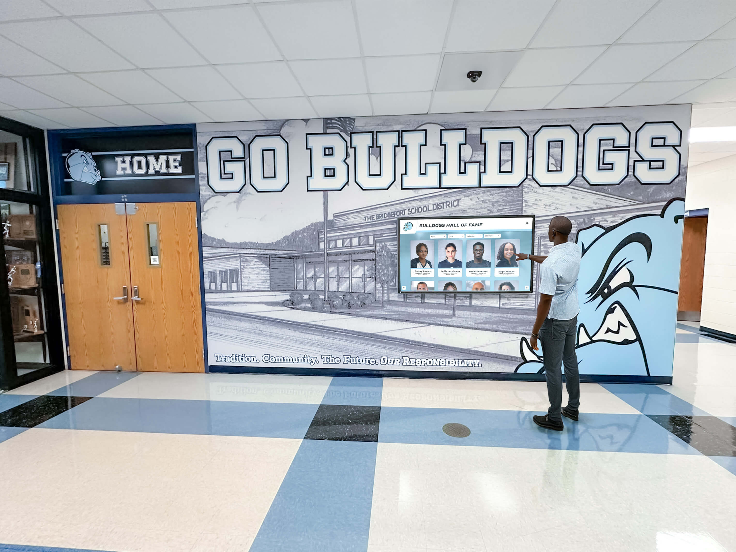
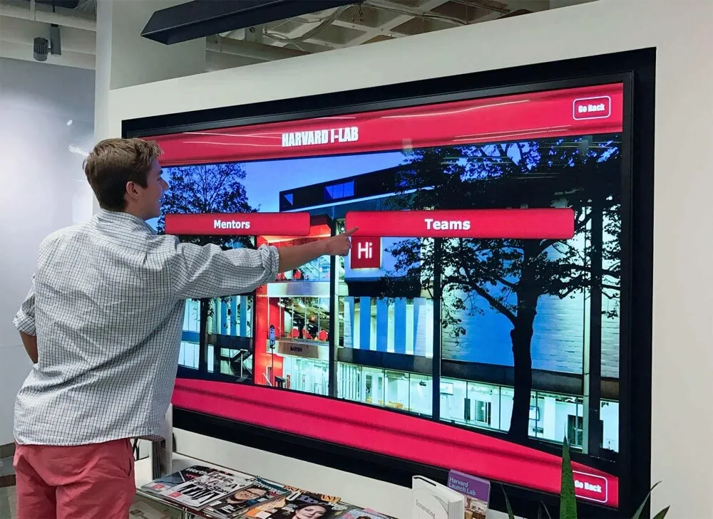
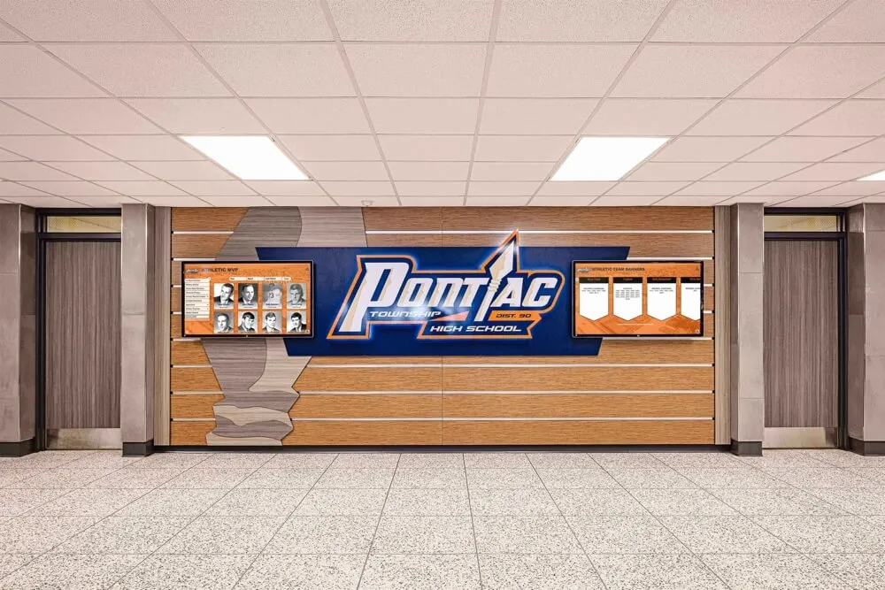
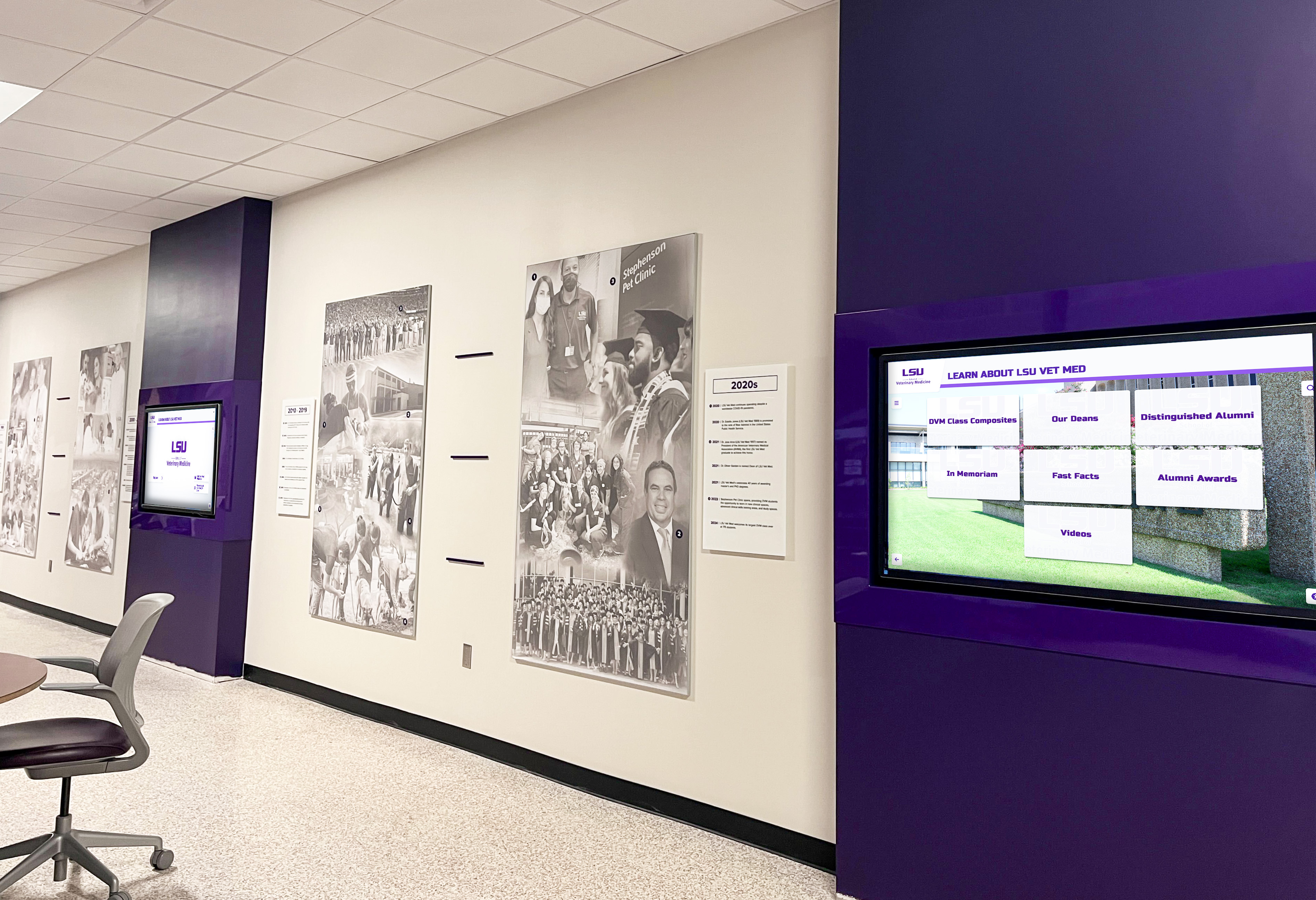
The most reliable LAG test verification is observing the recognition display directly — a team member at the screen during the simulated member failure confirms whether visual content interruption occurs
Step 5: Restore the Member Link and Verify Re-Convergence
A complete LAG test also validates that the failed member rejoins the aggregate cleanly after restoration. A member that recovers from a failure but does not re-enter the bundle reduces the uplink to a non-redundant single-link configuration until an administrator manually intervenes.
Step 5a: Re-enable the shut member port
interface GigabitEthernet1/0/1
no shutdown
Record the exact time of the no-shutdown command.
Step 5b: Confirm LACP re-negotiation
show lacp <n> internal
show etherchannel <n> summary
Within the LACP timer window (30 seconds for long timers, 3 seconds for short timers), the recovered member should show P (bundled) status. If it shows I (individual) or s (suspended) after the timer expires, LACP is failing to re-negotiate. The most common cause is that the access switch port retains a stale LACP state—cycling the interface (shutdown / no shutdown again) typically clears it.
Step 5c: Verify traffic re-hashing across both members
After the member rejoins the bundle, run per-member counter checks again:
show interfaces GigabitEthernet1/0/1 counters
show interfaces GigabitEthernet1/0/2 counters
In most LAG implementations, existing flows do not re-hash to the restored member. The restored member begins carrying new flows that open after it rejoins the bundle. This is expected and correct behavior—existing recognition display connections continue on the surviving member link rather than experiencing a second disruption when the LAG re-converges.
Confirm that new traffic (ping streams initiated after recovery, or a triggered content refresh from the platform dashboard) shows the expected hash distribution between both members.
Step 5d: Repeat the failure simulation on the other member
For a two-member LAG, repeat Steps 4c through 4f for the second member link. This confirms that redundancy is symmetric—either member can fail without causing a display outage, not just the specific member that happened to not carry the display’s traffic flow in the first test.
Schools supporting athletic programs that recognize student achievement understand that redundancy means protecting against any single failure, not just the most convenient one to test.
Step 6: Test During an Active Content Update
The most realistic LAG test runs during an active content push from the recognition platform, not only during idle periods. Schedule the failure simulation to coincide with a manual or triggered content update:
Step 6a: Trigger a content update from the platform dashboard
Using the recognition platform’s management interface, trigger a full content refresh or push a new athlete profile to the display while actively monitoring the per-member traffic counters. Confirm that content update traffic (larger packet sizes, sustained throughput for 10-30 seconds) appears on the expected member link.
Step 6b: Simulate the member failure mid-update
While the content update is transferring, administratively shut the carrying member link and watch:
- Whether the content update completes successfully on the surviving member
- Whether the display shows any visible freezing or black-screen behavior during the transfer interruption
- How long the content platform takes to resume the interrupted transfer after LAG failover
Some content platforms include retry logic that automatically resumes an interrupted update after the network path recovers. Others require the platform to re-schedule the update on its next automatic cycle. Documenting this behavior before a live athletic event ensures school staff know what to expect if a real uplink failure occurs during scheduled content delivery.

Schools where multiple recognition screens share a single aggregated uplink should test LAG failover behavior while a content update is actively delivering to confirm no manual IT action is needed after a real failure
Troubleshooting Common LAG Failures
Both Member Ports in LACP Passive Mode
Symptom: LAG negotiates successfully initially but fails to recover after one member goes down and comes back up. Alternatively, the LAG never negotiates after a switch reboot.
Cause: Both sides of the link are configured for LACP passive mode. Passive mode means neither side initiates LACP PDUs—each waits for the other to start. When both sides are passive, LACP negotiation never begins.
Resolution: Configure at least one side of the uplink—typically the access-layer switch—for LACP active mode:
interface GigabitEthernet1/0/1
channel-group 1 mode active
interface GigabitEthernet1/0/2
channel-group 1 mode active
The distribution switch can remain passive. Many network designs configure distribution switches as passive to allow any attached access switch to initiate LAG negotiation without the distribution switch sending unnecessary PDUs to switches that do not support LACP.
Member Link Suspended Due to Speed or Duplex Mismatch
Symptom: One member link shows s (suspended) in the etherchannel summary. The LAG appears to have only one active member.
Cause: Cisco IOS suspends a LAG member if it detects that the member’s operating parameters differ from the rest of the bundle. Common mismatches are a member port negotiating 100Mbps while others negotiate 1Gbps, or a port in half-duplex while the bundle operates full-duplex.
Resolution: Check the actual negotiated speed and duplex on the suspended port:
show interfaces GigabitEthernet1/0/1
Compare with the active member. If the suspended port shows a different speed or duplex, check:
- Cable type (Cat 5 cable versus Cat 5e/6 — a Cat 5 cable may negotiate correctly at 100Mbps but not at 1Gbps over longer runs)
- SFP transceiver compatibility — a third-party SFP in a Cisco switch may fail transceiver compatibility checks and operate at a reduced speed
- Auto-negotiation settings — if one port is set to forced 1Gbps/full and the switch port is auto, negotiation may fail
Minimum-Links Configuration Collapsing the LAG on Single Failure
Symptom: After shutting one member port in Step 4, the port-channel interface itself goes down rather than staying up with the surviving member.
Cause: port-channel min-links is configured equal to the total number of members. This setting is intended for bandwidth-critical deployments where a partial LAG is worse than a complete outage (for example, a storage array uplink where insufficient bandwidth causes data corruption). For a school recognition display uplink, this setting is almost never appropriate.
Resolution:
interface port-channel 1
port-channel min-links 1
Setting minimum-links to 1 ensures the logical interface stays up as long as at least one physical member is forwarding. After this change, re-run the failure simulation from Step 4 to confirm the fix.
Hashing Pinning All Display Traffic to One Member
Symptom: Per-member counters show one member handling nearly all traffic while the other member carries only spanning-tree and LACP protocol PDUs. When the loaded member fails, display outage occurs despite a surviving member being available.
Cause: The hashing algorithm produces the same hash value for all flows between the display’s single IP address and the content platform’s IP address. With src-ip hashing and a display with one source IP, all traffic always hashes to the same member.
Resolution: Change the hashing algorithm to include more flow entropy:
port-channel load-balance src-dst-ip
Or, for switches that support it:
port-channel load-balance src-dst-ip-l4port
After changing the hashing algorithm, re-run the traffic hashing verification in Step 3 to confirm the change takes effect and re-run the failure simulation in Step 4 to validate that the display’s traffic flows survive the identified member failing.
Pass/Fail Criteria and Test Documentation
Document the results of each test step using the following criteria. A LAG is considered validated for recognition display uplink use when all criteria pass.
| Test | Pass Criterion | Fail Condition |
|---|---|---|
| LACP negotiation | All configured members show P (bundled) state; no suspended or individual ports | Any member shows s, I, or D without a known reason |
| Member link health | No actively incrementing CRC or input errors on any member | CRC errors increasing between two CLI samples |
| Traffic hashing | At least one member carries display management and content traffic (counters increasing) | Display traffic absent from all members except during idle periods |
| Member failure failover | Port-channel interface remains up after single member failure; ping to display resumes within LACP timer window | Port-channel goes down, or ping does not recover within 30 seconds (long timers) or 5 seconds (fast timers) |
| Platform reconnection | Recognition platform shows display online within vendor’s documented reconnect window | Display remains offline on platform dashboard for more than 5 minutes after ping recovery |
| Member re-convergence | Failed member rejoins bundle within LACP timer window after restoration; existing traffic uninterrupted | Failed member shows I or s after timer expiry; traffic disruption occurs during re-join |
| Symmetric failure | Both member links independently pass the failure simulation | Only one member produces a clean failover; the other causes an outage |
| Mid-update failure | Content update completes or resumes automatically after failover | Content update requires manual re-trigger after failover |
Retain the completed test documentation with timestamps in the school’s network configuration change management records. This record is valuable both for confirming the initial LAG validation and as a baseline when troubleshooting future recognition display connectivity complaints—a failed LAG test that was passing on the last documented test date points directly to a change made between the two dates.
Schools that invest in recognizing student scholars and academic honorees alongside athletic achievement want those recognition systems available whenever the school community is present. Documented LAG validation is the network-layer foundation of that availability guarantee.

Completed and documented LAG testing converts a theoretical redundant uplink into a verified one — giving IT teams and athletic directors confidence the display stays available during the scheduled events that matter most
LACP Fast Timers: Reducing Failover Time for Recognition Display Uplinks
By default, LACP uses a 30-second PDU interval (slow rate). This means that when a member link fails, the switch waits up to 90 seconds (3× the PDU interval) before declaring the neighbor lost and removing the failed member from the bundle. For most campus uplinks, 90-second convergence is acceptable. For a recognition display in a lobby that a visiting recruiter or award ceremony attendee is actively viewing, a 90-second black screen is not acceptable.
LACP fast timers change the PDU interval to 1 second, reducing the maximum convergence time to 3 seconds. Enable fast timers on both the access-layer and distribution switches on the member ports participating in the recognition display uplink LAG:
interface GigabitEthernet1/0/1
lacp rate fast
interface GigabitEthernet1/0/2
lacp rate fast
Both ends of each member link must match—fast timers on one end and slow timers on the other prevents LACP from maintaining a stable session. Confirm the rate after configuration:
show lacp <n> internal
The timeout field should show S (short/fast) rather than L (long/slow) after the change. Re-run the failover timing measurement in Step 4e to confirm the reduced convergence window.
For schools that run recognition content during swim meets, YMCA athletic events, and multi-sport seasons where lobby displays are visible throughout the day, fast LACP timers transform a tolerable but visible interruption into a sub-perceptible one.
Scheduling LAG Tests in the School Maintenance Calendar
A LAG validation is not a one-time activity. Schedule re-validation after any of the following events:
- Switch replacement or firmware upgrade on either the access or distribution switch in the uplink path
- Cable or SFP transceiver replacement on any member link
- VLAN re-assignment for the recognition display segment
- Addition or removal of member links from the LAG
- Network security policy changes (802.1X, port security, storm control) applied to member ports
- After any unexplained recognition display connectivity complaint that was resolved without a clear root cause
Annual proactive testing—scheduling a controlled member-failure simulation during a summer or holiday break maintenance window—catches configuration drift that accumulates as switches are patched, replaced, and reconfigured over time. A LAG that validated cleanly at deployment may have had its minimum-links setting inadvertently overwritten during a configuration push six months later.
Schools that recognize student accomplishments through yearbook traditions and milestone honors understand that recognition systems require ongoing maintenance to remain meaningful. The same discipline applies to the network infrastructure that delivers those recognition experiences.
Making Link Aggregation Testing Part of Recognition Display Deployment
For school IT teams deploying a new recognition display or migrating an existing one to a different network segment, the LAG test should be a formal checkpoint in the deployment checklist—completed and signed off before the recognition system goes live and before athletic staff or administrators are informed the display is ready for use.
The sequence that works well in practice:
- Configure and document the LAG on both switches before the display hardware arrives.
- Run Steps 1 through 3 (negotiation, member health, traffic hashing) using test traffic from a laptop connected to the display’s switch port.
- Simulate member failures with the test laptop to confirm failover without a recognition display at risk.
- Connect the recognition display and run Steps 4 through 6 with actual platform traffic.
- Sign off and hand the display to athletic staff with a documented LAG validation record.
This sequence means the failure simulation—which temporarily disrupts switch uplink redundancy—happens before the display is in production use, eliminating any risk to students or staff who may be viewing the display during the test.
Recognizing championship wrestlers, award recipients, and program milestones is exactly the kind of content that schools invest in digital recognition displays to deliver. A validated, redundant network uplink ensures that investment delivers reliably—regardless of whether a cable snags, a transceiver ages out, or a facilities crew accidentally disconnects the wrong port during a nearby construction project.
Ready to Deploy a Recognition Display That's Built for Reliability?
Rocket Alumni Solutions provides school IT teams with network compatibility documentation, deployment checklists, and ongoing technical support for recognition display installations. Whether your uplink uses link aggregation, 802.1X, DAI, or other campus security controls, our team can align the deployment to your network's requirements.
Request a Recognition Display DemoA school recognition display link aggregation test is a structured, repeatable procedure that converts a theoretically redundant uplink into a documented, verified one. By confirming LACP negotiation, member-link health, traffic hashing, and failover behavior under controlled conditions, school IT teams eliminate the most common source of unexpected display outages—and give athletic directors, administrators, and facilities staff the confidence to schedule recognition events without worrying about the network infrastructure beneath them.