

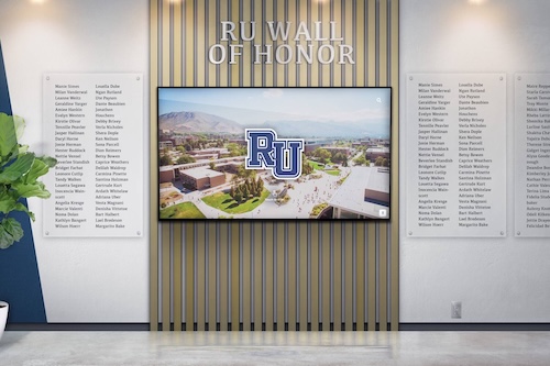
A school recognition display in a gymnasium or lobby hallway can appear fully operational from every surface-level check — the screen is on, the link light is green, the platform dashboard shows the device as online — yet still deliver sluggish video sync, missed content updates, and intermittent frame drops when the fiber uplink carrying its traffic is operating near the edge of acceptable optical power. Fiber uplinks do not fail cleanly. A transceiver whose receive power has drifted into the marginal range continues to pass traffic, but with elevated bit-error rates and retransmissions that cause the exact symptoms school IT teams often attribute to content platform performance or Wi-Fi interference. The problem is in the glass and the laser, not the software.
Digital Optical Monitoring (DOM), also called Digital Diagnostics Monitoring (DDM), is a capability built into modern SFP, SFP+, and QSFP fiber transceivers that reports real-time optical performance values — transmit power, receive power, temperature, supply voltage, and laser bias current — directly through the switch CLI. A structured school recognition display SFP DOM health check reads these values from the fiber uplink serving a display’s access switch, compares them against the transceiver’s alarm and warning thresholds, and identifies marginal links before they cause a content delivery failure during a recognition ceremony or athletic event.
Quick answer: A fiber uplink serving a school recognition display is healthy when the transceiver’s DOM values fall within these ranges: RX power above −20 dBm (warning threshold), TX power within ±3 dB of the transceiver’s rated output, temperature below 70 °C, supply voltage between 3.1 V and 3.5 V, and laser bias current within the vendor’s specified range. Read these values with show interfaces transceiver on Cisco IOS, show transceiver all on HP/Aruba, or show interfaces diagnostics optics on Juniper. An alarm or warning flag on any parameter means the uplink is marginal and should be investigated before the display is expected to deliver synchronized content at a school event.

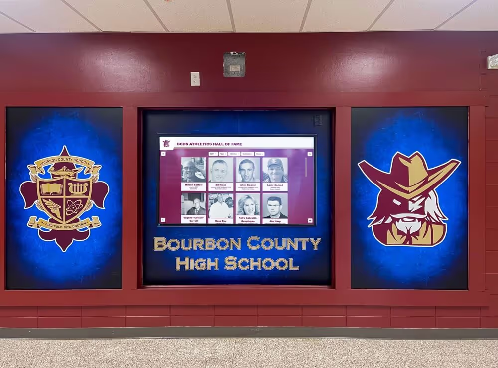
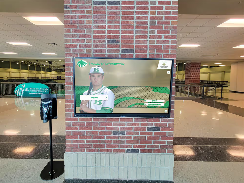
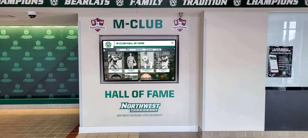
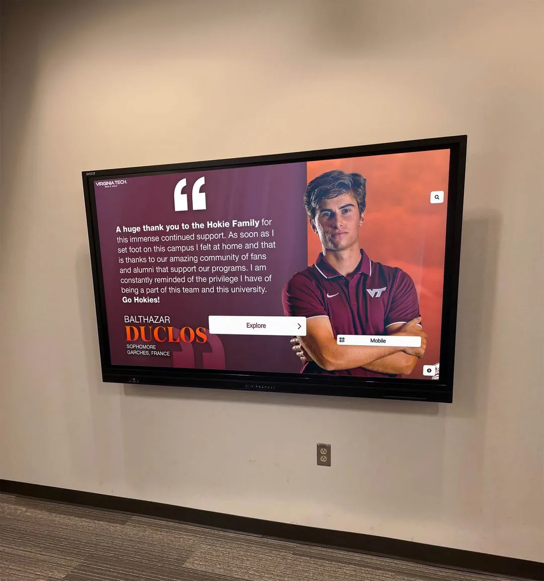
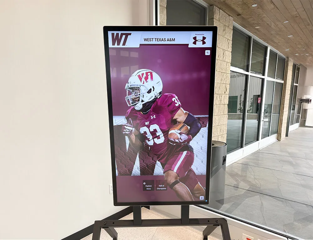
A recognition display kiosk depends on the fiber uplink feeding its access switch — SFP DOM health checks catch marginal transceivers before optical power drift causes content sync failures during a ceremony or game-day event
What SFP DOM Is and Why It Matters for School Recognition Displays
Small Form-factor Pluggable (SFP) transceivers are the modules that convert electrical signals to optical signals (and back) on fiber uplinks between access-layer switches and distribution-layer or core switches in a school network. Every recognition display’s Ethernet connection ultimately depends on one or more of these fiber uplinks to reach the content delivery platform that keeps it synchronized.
Digital Optical Monitoring (DOM) is a standardized interface, defined in SFF-8472, that allows a DOM-capable transceiver to report five real-time performance parameters through a two-wire serial interface that the switch reads on demand:
| DOM Parameter | What It Measures | Why It Matters for Recognition Displays |
|---|---|---|
| TX Power | Optical power emitted by the transceiver’s laser, in dBm | Low TX power causes the far-end receiver to drop below its sensitivity threshold; content sync fails |
| RX Power | Optical power arriving at the transceiver’s photodetector, in dBm | The most diagnostic value — low RX power directly predicts bit errors, retransmissions, and throughput collapse |
| Temperature | Internal transceiver temperature in degrees Celsius | Overheating causes laser wavelength drift and reduced output power; wiring closets near mechanical rooms are at risk |
| Supply Voltage | Voltage supplied to the transceiver by the switch, in volts | Out-of-spec voltage degrades laser output and shortens transceiver life |
| Bias Current | Electrical current driving the transmit laser diode, in milliamps | Rising bias current compensating for laser aging is an early indicator that the transceiver is approaching end of life |
Each DOM-capable transceiver stores four threshold values for each parameter: a high alarm, a high warning, a low warning, and a low alarm. These thresholds are set by the transceiver manufacturer and stored in the module’s EEPROM. When a live value crosses a threshold, the switch CLI shows an alarm or warning flag that the IT administrator can query without any external test equipment.
For school networks where fiber uplinks run through conduit from an IDF closet in a gymnasium hallway to the building’s MDF, the transceiver at each end of that fiber span is the component most likely to degrade silently over a multi-year deployment. Athletic hall of fame kiosks, digital trophy case screens in lobby display cases, and donor recognition panels all depend on those uplinks staying within optical performance spec.
How Marginal Fiber Uplinks Affect Recognition Display Content Delivery
A fiber uplink degraded to the −20 to −23 dBm RX power range — within the warning zone but not yet alarming — does not drop the link. The switch still reports the port as up. The recognition display platform still shows the device as connected. But the bit-error rate on that link rises. Higher bit-error rates mean more TCP retransmissions. More retransmissions mean that large content payloads — high-resolution athlete portrait updates, video highlight clips for an athletic record board, full content library syncs — take significantly longer to complete than they would on a clean fiber span.
The timing of the failures is what makes a marginal fiber uplink difficult to diagnose without DOM data. Content delivery problems appear during scheduled sync windows, during event-day content pushes, and during peak school-hours traffic when the uplink is under higher utilization. At night, with minimal traffic, the same marginal link delivers small management packets reliably, and a ping test from the display to the internet returns clean results. The IT team checks the display, finds no obvious fault, and returns to other work.
Schools that maintain recognition programs spanning multiple digital record boards and campus engagement installations cannot afford this diagnostic gap. The SFP DOM health check closes it by providing an objective, CLI-readable measurement of the uplink’s actual optical condition — independent of traffic load, time of day, or platform status.
SFP DOM Signal Value Reference Table
Use this table to interpret DOM readings for fiber uplinks serving school recognition display switches. Values shown are typical for 1000BASE-LX single-mode SFP transceivers commonly used in school network uplinks; always compare against the transceiver vendor’s datasheet for the exact module installed.
| Parameter | Normal Range | Warning Threshold | Alarm Threshold | Action When Alarmed |
|---|---|---|---|---|
| RX Power | −3 to −20 dBm | −20 to −23 dBm | Below −23 dBm | Clean connectors; inspect fiber; replace transceiver |
| TX Power | 0 to −5 dBm (LX typical) | ±2 dB from rated | ±3 dB from rated | Replace transceiver; verify launch conditions |
| Temperature | 0 to 70 °C | 70 to 80 °C | Above 80 °C | Improve wiring closet ventilation; check airflow |
| Supply Voltage | 3.1 to 3.5 V | 3.0 to 3.1 V or 3.5 to 3.6 V | Below 3.0 V or above 3.6 V | Reseat transceiver; inspect switch power delivery |
| Bias Current | 2 to 60 mA (vendor-specific) | Approaching high threshold | At or above high alarm | Transceiver aging; plan replacement |
Short-reach multi-mode SFP transceivers (1000BASE-SX) used for intra-building fiber runs have different typical RX power ranges — usually −3 to −17 dBm — because multi-mode fiber carries higher optical power over shorter distances. Check the specific transceiver’s datasheet before interpreting RX power values on a multi-mode span.
Pre-Check: Identifying the Uplink SFP to Test
Before running DOM queries, identify which SFP interfaces on which switches are part of the fiber path between the recognition display’s access switch and the rest of the network. Querying the wrong interface returns valid DOM data that has no bearing on the display’s connectivity.
| Information Needed | How to Collect It | Why It Matters |
|---|---|---|
| Access switch identity | Check the IP asset register or trace the display’s Ethernet cable to its switch | DOM must be read from the switch the display connects to, and from the uplink on that switch |
| Uplink port identifier | show lldp neighbors or show cdp neighbors on the access switch — the uplink to the distribution layer appears as a neighbor | DOM is only relevant on the fiber uplink port, not on the copper access port where the display’s patch cable connects |
| Transceiver module type | show interfaces transceiver — the module type appears in the output | Determines which threshold values to reference from the vendor’s datasheet |
| Fiber connector cleanliness | Visual inspection with a fiber inspection microscope or end-face cleaner | A dirty connector is the most common cause of low RX power and can be fixed without replacing hardware |
| Switch CLI access | SSH to the access switch with credentials sufficient to run show commands | Cannot read DOM values without management access |
If LLDP neighbor data is not available, checking the fiber patch panel label at the IDF and the switch port the cable connects to provides the interface identifier needed for DOM queries.
Numbered SFP DOM Health Check Procedure
Step 1: Verify the Transceiver Supports DOM
Not all SFP transceivers implement DOM. Older or low-cost modules may not expose optical monitoring data. Confirm DOM capability before expecting output.
Cisco IOS / IOS-XE:
show interfaces GigabitEthernet1/1/1 transceiver
If the transceiver supports DOM, the output includes the current measurements:
        Transceiver Temperature     : 34.8 C
        Transceiver Voltage         : 3.29 V
        Transceiver Tx Bias Current : 8.3 mA
        Transceiver Tx Power        : -2.4 dBm
        Transceiver Rx Optical Power: -8.7 dBm
If the output returns only the module type and serial number with no measurement rows, the transceiver is either a non-DOM module or DOM is not enabled for that interface. In that case, skip to Step 7 and note the limitation in the asset record.
HP / Aruba ProCurve:
show transceiver all
Juniper EX:
show interfaces ge-0/0/48 diagnostics optics
Step 2: Read Current DOM Values
After confirming DOM support, read the full diagnostic output including alarm and warning flags.
Cisco IOS — full transceiver detail:
show interfaces transceiver detail
This command prints all DOM-capable interfaces with their current values and any active alarm or warning flags:
ITU Channel not available (Wavelength not available),
Transceiver is internally calibrated.
mA: milliamperes, dBm: decibels (milliwatts), NA or N/A: not applicable.
++ : high alarm, +  : high warning, -  : low warning, -- : low alarm.
A2D readouts (if they differ), are transceiver calibrated.

                              Optical   Optical
           Temperature Voltage  Tx Power  Rx Power  Tx Bias
Port       (Celsius)  (Volts)   (dBm)     (dBm)    Current
                                                    (mA)
--------- ----------- -------  --------  --------  -------
Gi1/1/1     34.8       3.29     -2.4      -8.7      8.3
Gi1/1/2     36.1       3.28     -2.2     -21.5 -    8.8
Gi1/1/3     35.0       3.30     -2.5     -25.3 --   8.5
In this example output: Gi1/1/2 has a low warning on RX Power (−21.5 dBm, flagged with -), and Gi1/1/3 has a low alarm on RX Power (−25.3 dBm, flagged with --). Both interfaces warrant immediate attention if they are carrying traffic to recognition display switches.
Step 3: Compare Values Against Alarm and Warning Thresholds
Read the alarm and warning threshold values stored in the transceiver itself:
show interfaces GigabitEthernet1/1/1 transceiver detail
On IOS-XE the detailed output includes the alarm and warning table:
  Transceiver Type            : SFP-GE-L
  Wavelength                  : 1310 nm
  Threshold Values
                         High Alarm   High Warn    Low Warn     Low Alarm
                         ----------   ---------    --------     ---------
  Temperature (C)           85.0         75.0        -5.0        -15.0
  Voltage (V)                3.6          3.5         3.1          3.0
  Tx Bias (mA)              60.0         50.0         2.0          1.0
  Tx Power (dBm)             0.0         -1.0        -7.0         -8.0
  Rx Power (dBm)            -3.0         -4.0       -20.0        -23.0
Map each current value from Step 2 against the Low Warn and Low Alarm thresholds. Any current value that has crossed the Low Warn threshold for RX Power — meaning it is below −20.0 dBm in this example — is a marginal uplink that should be documented and investigated. Any current value at or below the Low Alarm threshold (−23.0 dBm) is a link at risk of failing outright under load.
Step 4: Record Baseline Values for All Display-Serving Uplinks
For a clean uplink with all values in the normal range, record the current DOM values in the switch documentation as a baseline. DOM values naturally shift slightly with ambient temperature and over the transceiver’s lifetime; having a documented baseline makes it possible to detect drift between inspection cycles.
| Uplink Interface | Switch | Date Recorded | TX Power (dBm) | RX Power (dBm) | Temp (°C) | Voltage (V) | Bias (mA) | Status |
|---|---|---|---|---|---|---|---|---|
| Gi1/1/1 | SW-IDF-GYM | 2026-09-15 | −2.4 | −8.7 | 34.8 | 3.29 | 8.3 | Normal |
| Gi1/1/2 | SW-IDF-GYM | 2026-09-15 | −2.2 | −21.5 | 36.1 | 3.28 | 8.8 | Low Warning — RX |
| Gi1/0/2 | SW-IDF-LOBBY | 2026-09-15 | −2.6 | −9.1 | 33.5 | 3.30 | 8.1 | Normal |
| Gi1/0/2 | SW-IDF-HALL | 2026-09-15 | −2.3 | −12.4 | 35.2 | 3.29 | 8.4 | Normal |
This table becomes the reference for the next quarterly inspection cycle. An RX power reading that was −8.7 dBm at installation and has moved to −16.0 dBm two years later indicates gradual degradation in the fiber span — connector contamination, connector wear, or micro-bending — that will eventually reach the warning threshold if not addressed.
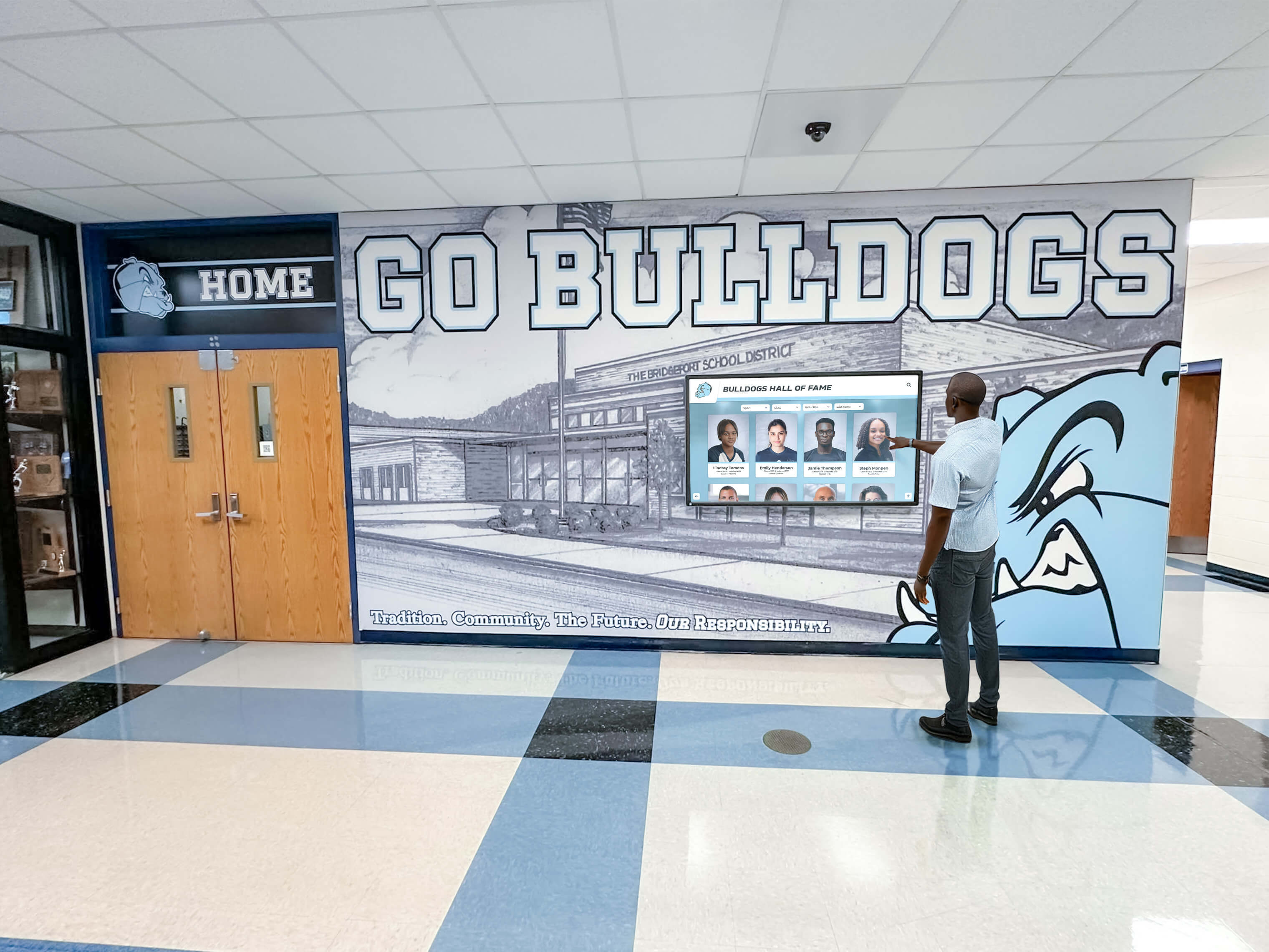
DOM baseline records from installation give school IT teams a reference point to compare against during annual inspections — gradual RX power drift shows up as a trend before it becomes an alarm
Step 5: Clean Fiber Connectors Before Replacing Hardware
Low RX power is most often caused by contaminated fiber connectors — dust, oils, and microscopic debris on the end-face of an LC or SC connector cause insertion loss that directly reduces the received optical power. Before replacing a transceiver or fiber cable, clean all connectors in the optical path and re-read the DOM values.
Fiber end-face cleaning procedure:
- Power down the uplink if the switch allows hitless transceiver removal; otherwise proceed carefully to avoid a content delivery gap
- Use a fiber end-face cleaner (reel-style or cassette) rated for the connector type (LC, SC, or MPO)
- Clean the transceiver port on the switch with a port-cleaning swab before re-inserting the fiber
- Clean the far-end transceiver in the same way
- Re-seat the fiber connectors firmly
- Wait 60 seconds for the link to re-establish, then re-read the DOM values with
show interfaces transceiver
If RX power returns to the normal range after cleaning, document the cleaning date in the asset record. If RX power remains below the warning threshold after cleaning, the fiber cable or one of the transceivers requires replacement.
Step 6: Evaluate Temperature and Voltage Values
While RX power is the primary diagnostic for most school network fiber uplinks, temperature and voltage anomalies indicate problems that will shorten transceiver life and eventually affect the recognition displays the uplink serves.
Temperature alerts in wiring closets serving gymnasiums, locker rooms, and mechanical spaces are common in school facilities because these areas have variable HVAC coverage. A transceiver at 78 °C — in the warning range — operates with reduced laser output efficiency and higher laser aging rates. Improving wiring closet airflow, adding a rack-mounted exhaust fan, or scheduling an HVAC inspection for that space resolves the root cause. Reducing temperature to the 35–45 °C typical range also reduces bias current and extends the transceiver’s useful life.
Voltage anomalies are uncommon on well-maintained switches but can appear after a power supply failure, a partial switch failure, or on older switches near end of life. A supply voltage outside the 3.1–3.5 V range for an SFP should trigger a switch inspection, not just a transceiver replacement.
Step 7: Document Non-DOM Transceivers and Plan Replacements
If any uplink serving a recognition display switch contains a non-DOM transceiver — identified in Step 1 by the absence of measurement output — document that limitation and plan to replace it with a DOM-capable equivalent at the next maintenance window.
Non-DOM transceivers are common in older school networks where switches were purchased with bundled fiber modules rather than standards-compliant SFPs. Running without DOM on an uplink serving a recognition display means the IT team has no early-warning visibility into optical power degradation — the first sign of a problem will be a content delivery failure, not a CLI flag.
Replacement transceivers must be compatible with the switch’s SFP cage and validated for the fiber type (single-mode or multi-mode) and span length in use. Many switch vendors validate third-party DOM-capable SFPs alongside their own branded modules; check the vendor’s transceiver compatibility matrix for the specific switch model before purchasing replacements.
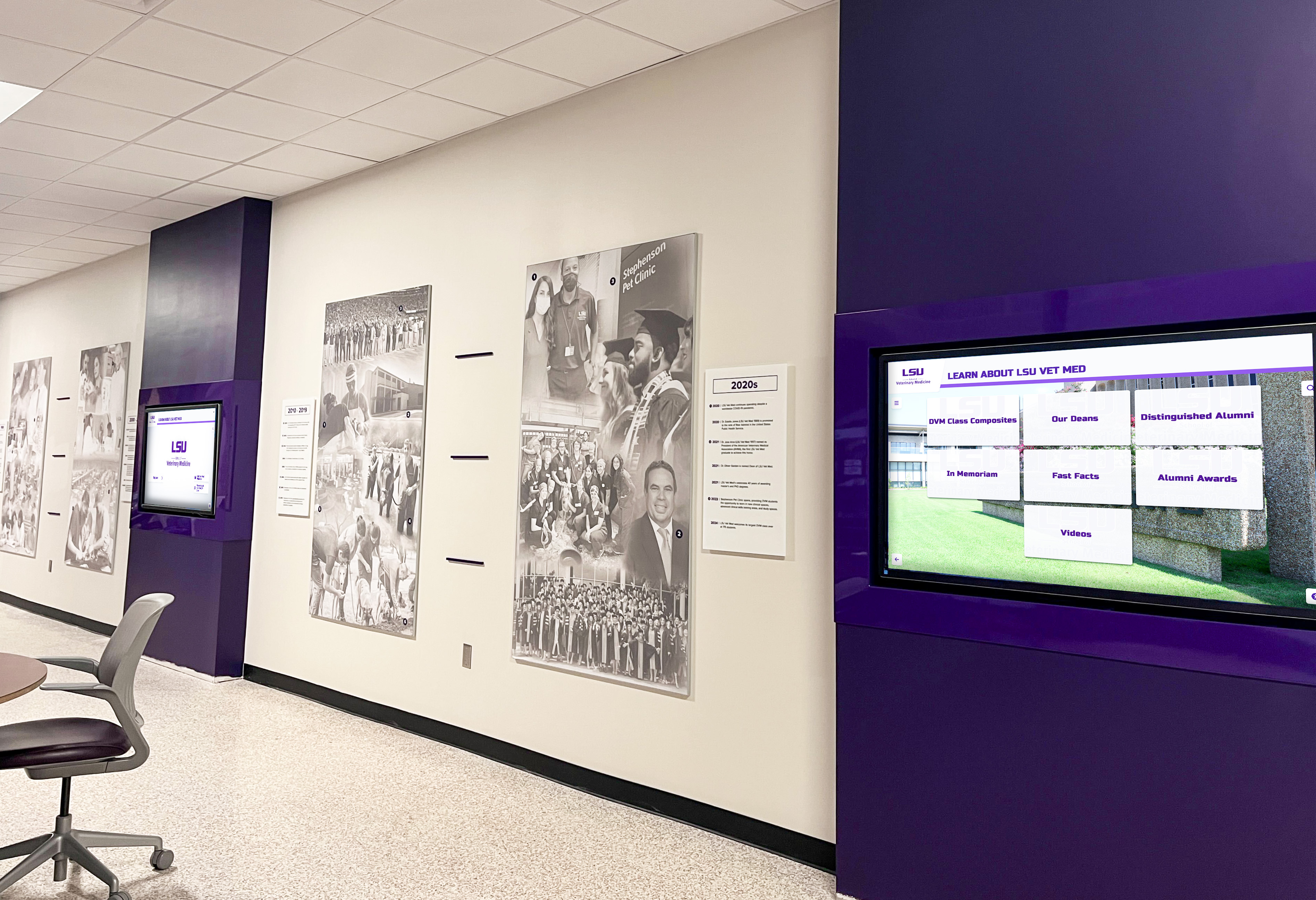
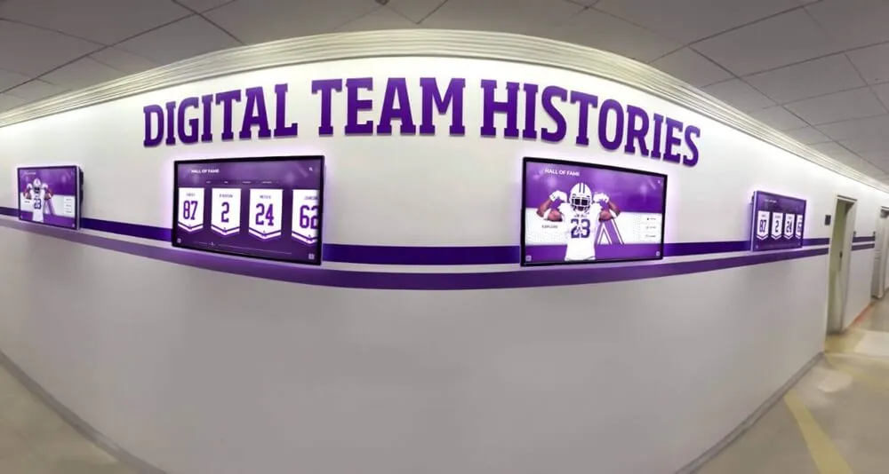
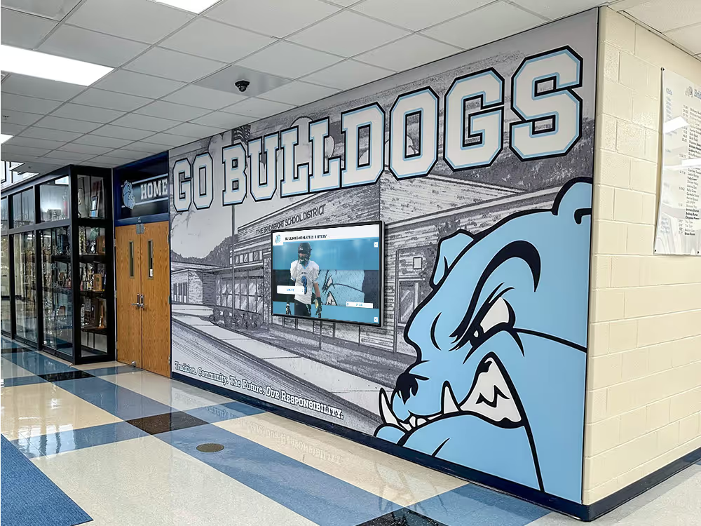
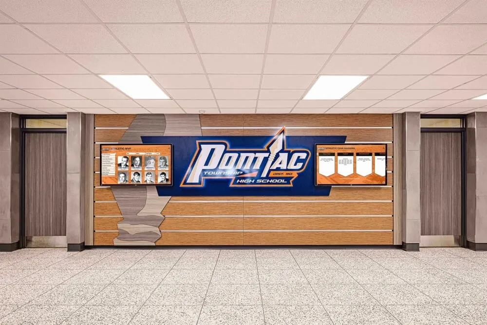
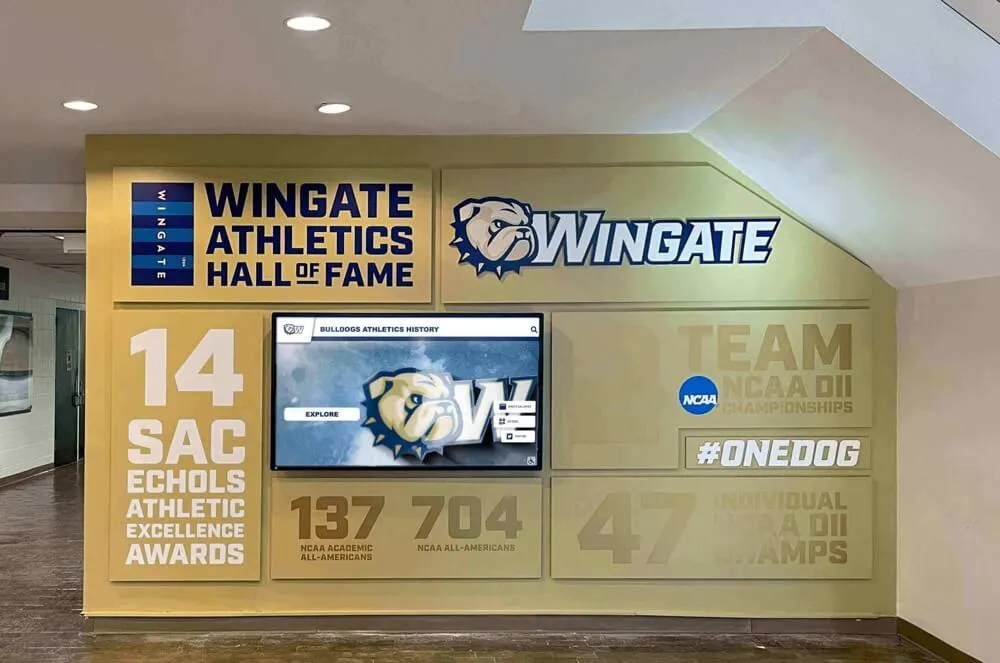
Hallway recognition displays that cycle through team histories and athlete records depend on clean fiber uplinks — DOM monitoring gives IT teams the ability to detect and resolve optical degradation before visitors see a stale or blank screen
Step 8: Test Under Load After Any Remediation
After cleaning connectors, replacing a transceiver, or improving wiring closet cooling, run a load test on the recognition display to confirm that content delivery has returned to baseline performance:
- Trigger a full content sync from the platform dashboard — this pushes the largest available content payload to the display
- Monitor the sync completion time against the expected value documented at installation
- While the sync runs, re-read DOM values to confirm RX power remains stable under traffic load
- Check the switch port statistics for the display’s access port for any new error counters:
show interfaces GigabitEthernet1/0/18
Look for incrementing CRC errors, input errors, or giants after remediation. These counters should be zero or stable after a successful repair. If they continue to increment, the fiber span may have a physical fault — micro-bending, a pinched cable, or a damaged connector — that cleaning and transceiver replacement cannot fix.
Integrating SFP DOM Checks Into School IT Maintenance Cycles
A one-time DOM health check at installation creates a baseline. A repeating check schedule catches degradation before it reaches the alarm threshold. The inspection frequency depends on the school’s recognition program activity calendar:
| Inspection Point | Timing | Scope |
|---|---|---|
| Installation baseline | At display installation or uplink commissioning | All uplinks serving recognition display switches; record DOM values to asset documentation |
| Pre-event check | 48 hours before a major recognition ceremony, athletics banquet, or hall of fame induction | All uplinks serving displays that will be active during the event |
| Quarterly inspection | Every three months during low-activity periods | All recognition display uplinks; compare against baseline to identify drift |
| After any wiring work | Within 24 hours of fiber cable replacement, IDF closet work, or switch upgrade | Affected uplinks only; confirm connectors re-seated cleanly |
| Annual transceiver audit | Once per year | Identify any non-DOM transceivers; plan replacement for next budget cycle |
Schools that schedule recognition display network health checks on the same calendar as other AV maintenance — display calibration, cable strain relief inspection, and platform software updates — reduce the risk of event-day failures without adding a separate IT workflow. This proactive approach mirrors the discipline that school IT teams apply to network inventory accuracy, where documentation maintained before a problem occurs is far more useful than documentation created during an incident.
Fiber uplink health is foundational to reliable recognition display delivery. Rocket Alumni Solutions works with school IT and AV teams to document network requirements, identify compatibility risks, and keep digital hall of fame displays, athletic record boards, and alumni recognition kiosks performing through every event on the school calendar.
SFP DOM Alarm and Warning Reference by Parameter
Use this consolidated reference when reviewing DOM output from any switch CLI. The flag characters shown apply to Cisco IOS; other vendors display similar indicators in their own output format.
RX Power (Receive Optical Power)
RX power is the most operationally significant DOM parameter for school network fiber uplinks. It represents the optical signal arriving at the transceiver after traveling through the fiber cable and all connectors between the two endpoints.
| RX Power Reading | Flag | Meaning | Action |
|---|---|---|---|
| Above −3 dBm | High Warning or Alarm | Fiber span too short; possible reflections | Verify fiber distance; insert attenuator if required |
| −3 to −20 dBm | None | Normal operating range | Document baseline; no action required |
| −20 to −23 dBm | - (Low Warning) | Marginal; approaching sensitivity limit | Clean connectors; re-test; schedule remediation |
| Below −23 dBm | -- (Low Alarm) | At or below receiver sensitivity; errors likely | Immediate remediation required; clean or replace |
TX Power (Transmit Optical Power)
TX power degradation is less common than RX power issues but indicates laser aging or a failing transceiver on the transmitting end.
| TX Power Reading | Flag | Meaning | Action |
|---|---|---|---|
| Above rated + 1 dBm | High Warning | Laser overcurrent; check bias current | Inspect transceiver; may indicate control circuit issue |
| Within ±1 dBm of rated | None | Normal | Document baseline; no action required |
| 2 to 3 dBm below rated | - (Low Warning) | Laser aging or thermal effect | Monitor at next inspection; check temperature |
| More than 3 dBm below rated | -- (Low Alarm) | Transceiver failure | Replace transceiver |
Temperature
| Temperature Reading | Flag | Meaning | Action |
|---|---|---|---|
| 0 to 70 °C | None | Normal operating range | No action |
| 70 to 80 °C | - or + (Warning) | Wiring closet overheating | Inspect closet cooling; add airflow |
| Above 80 °C | -- or ++ (Alarm) | Extreme thermal stress | Immediate cooling intervention; risk of failure |
Coordinating the Health Check With Recognition Event Schedules
The practical value of a structured SFP DOM health check is highest when it runs close enough to a recognition event to catch new issues without being so close that remediation cannot be completed before the event begins. A 48-hour pre-event window is the standard in school network environments: it provides enough lead time to schedule a maintenance window, clean or replace a transceiver, verify the fix, and confirm content sync has completed.
Schools with multiple recognition displays — lobby donor recognition panels, gymnasium hall of fame kiosks, and athletic corridor record boards — serve different audiences at different events. The athletic director managing a spring sports banquet depends on the gymnasium kiosk just as the principal managing a board presentation depends on the lobby display. Coordinating DOM check schedules with the recognition program calendar ensures that each display’s fiber uplink is confirmed healthy before the moment that audience arrives.
Schools connecting their recognition program to a broader campus engagement strategy — such as using digital record boards alongside other campus engagement ideas — benefit from treating the DOM health check as a standard part of that program’s operational checklist rather than a reactive troubleshooting step.
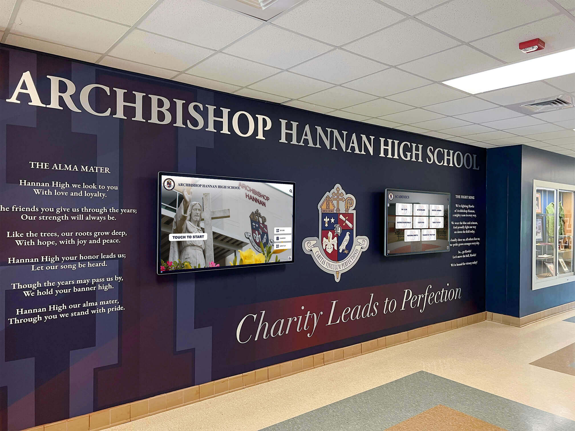
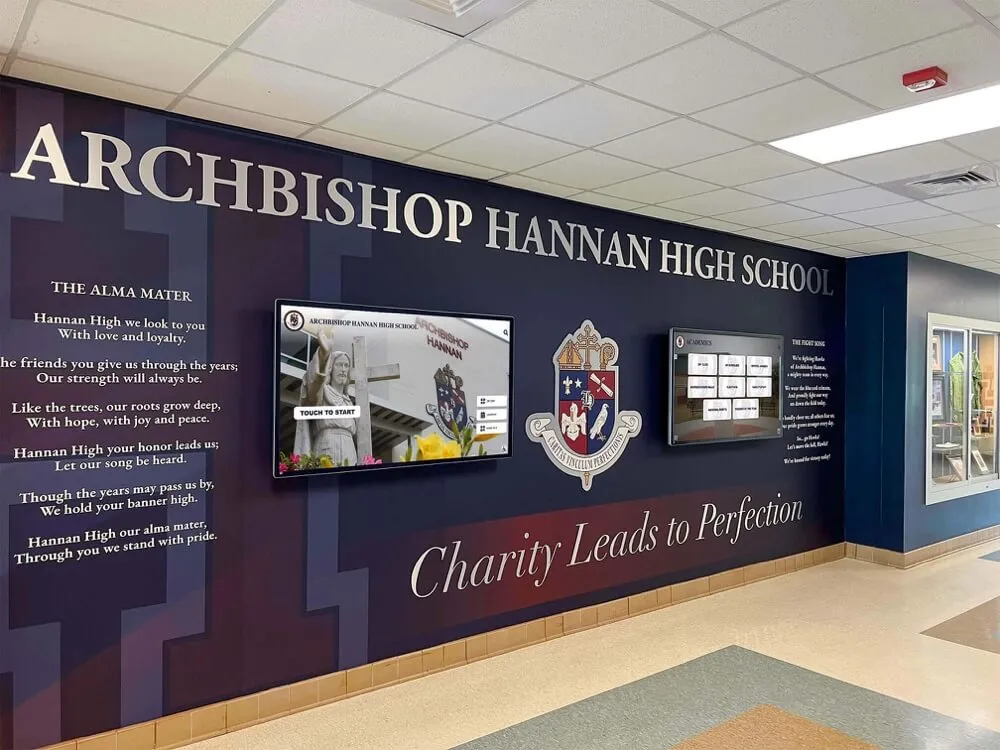
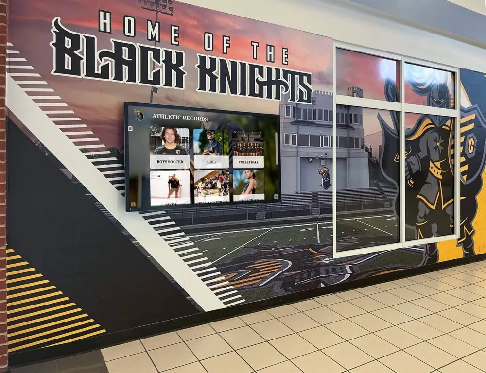
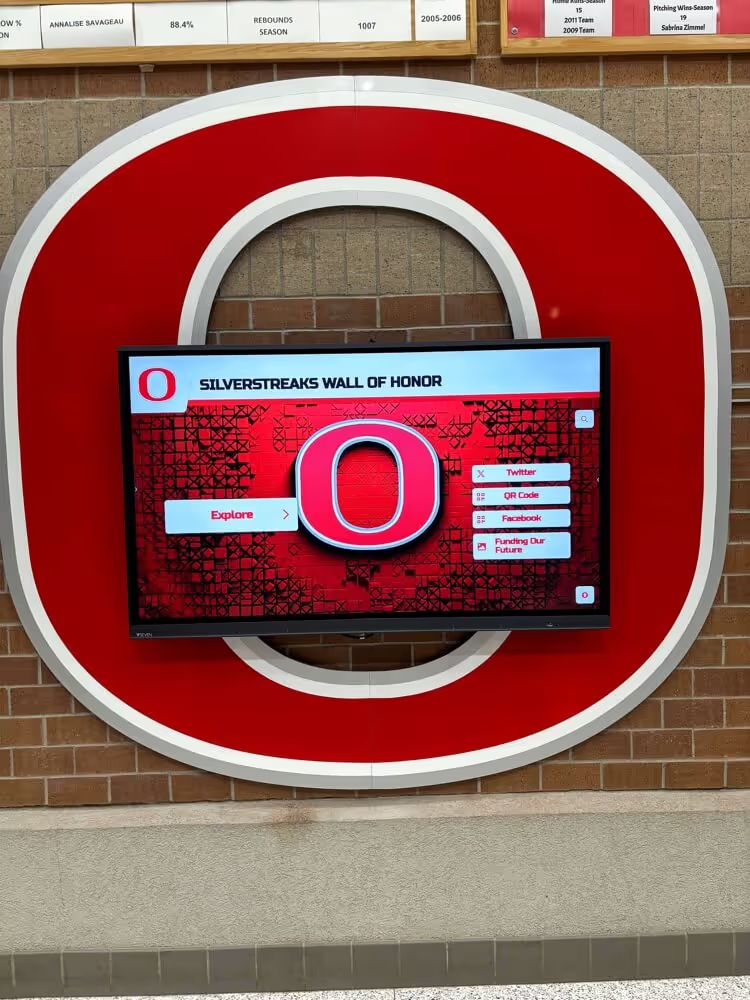
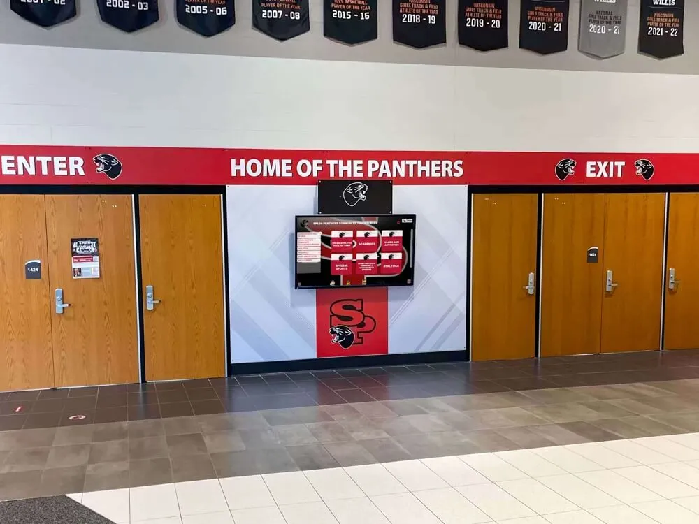
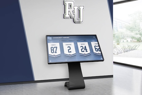
Lobby recognition displays embedded in school murals depend on fiber uplinks that remain within DOM specifications — quarterly health checks catch optical degradation before it becomes visible to visitors as a stale or blank screen
Frequently Asked Questions
What switch commands read SFP DOM values?
On Cisco IOS and IOS-XE, use show interfaces transceiver for a summary of all DOM-capable interfaces or show interfaces GigabitEthernet1/1/1 transceiver detail for one interface with threshold values. On HP/Aruba ProCurve, use show transceiver all. On Juniper EX, use show interfaces ge-0/0/48 diagnostics optics. On Extreme Networks, use show ports transceiver information.
How often should school IT teams run SFP DOM checks on recognition display uplinks? At minimum, once per quarter and within 48 hours before any major recognition event. Quarterly inspection catches gradual degradation trends between events; the pre-event check catches any new issues since the last inspection.
Does a fiber uplink with a low RX power warning always need to be replaced? Not immediately. The first remediation step is cleaning the fiber connectors at both ends of the span, which resolves the majority of low RX power warnings. If cleaning does not restore RX power to the normal range, the fiber cable or transceiver requires replacement.
Can SFP DOM values be monitored automatically without manual CLI checks? Yes. Most network management systems — including Cisco DNA Center, Aruba Central, SolarWinds, and PRTG — can poll DOM values via SNMP and generate alerts when values cross warning or alarm thresholds. Configuring automated DOM alerts for recognition display uplinks removes the dependency on scheduled manual checks.
What is the difference between SFP DOM and SFP+ DOM? SFP DOM refers to 1 Gbps form-factor transceivers. SFP+ DOM refers to 10 Gbps form-factor transceivers. Both implement the same SFF-8472 monitoring interface and expose the same five parameter categories. The threshold values and typical operating ranges differ between the two due to differences in laser power and receiver sensitivity.
What if the recognition display’s access switch does not support DOM queries? Unmanaged switches and very old managed switches may not support DOM queries through the CLI. In that case, the only option for checking optical health is an external optical power meter placed inline at the fiber connector. Planning for a managed switch replacement at the next budget cycle adds DOM visibility to all uplinks without requiring ongoing manual power measurements.
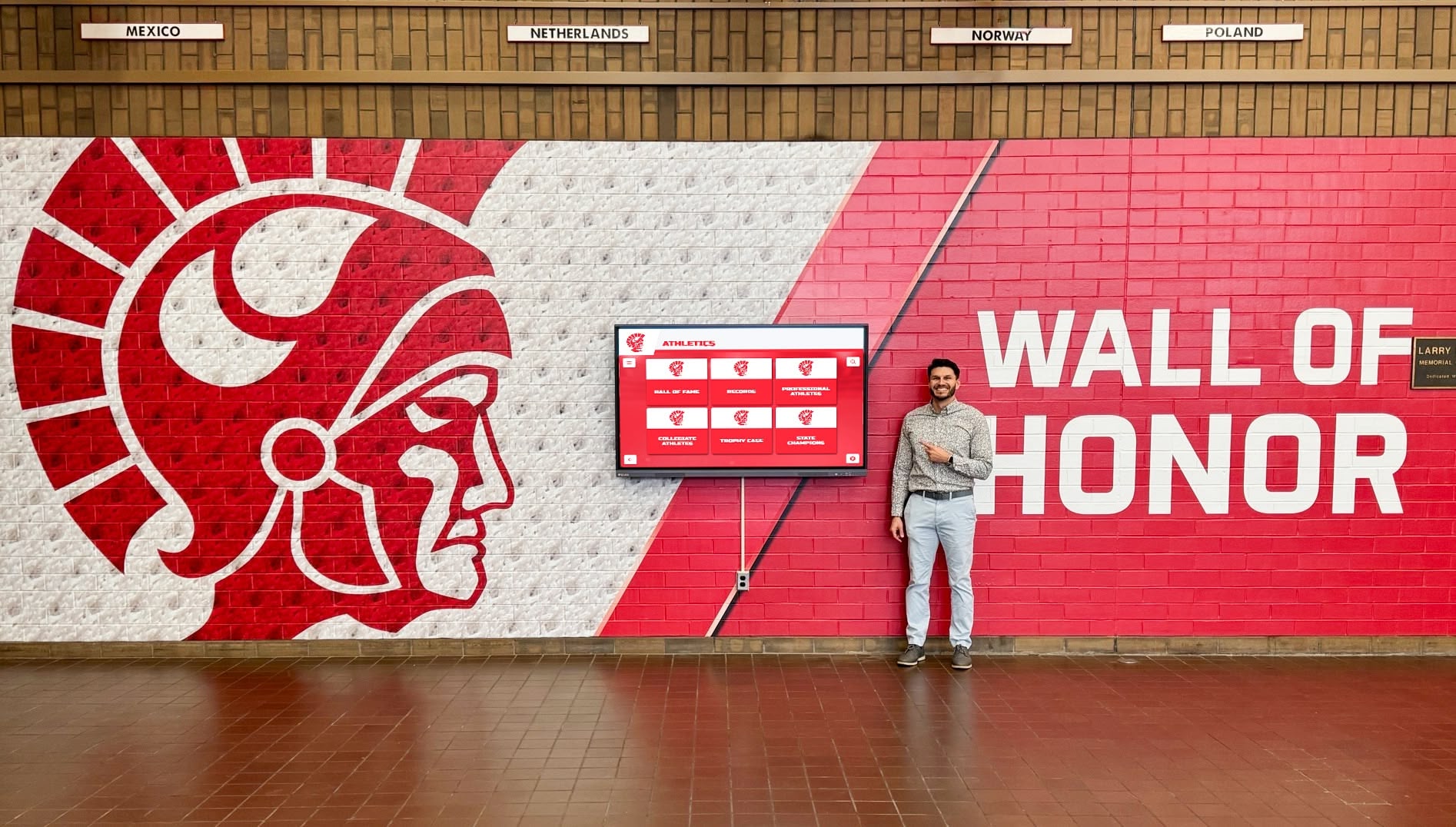
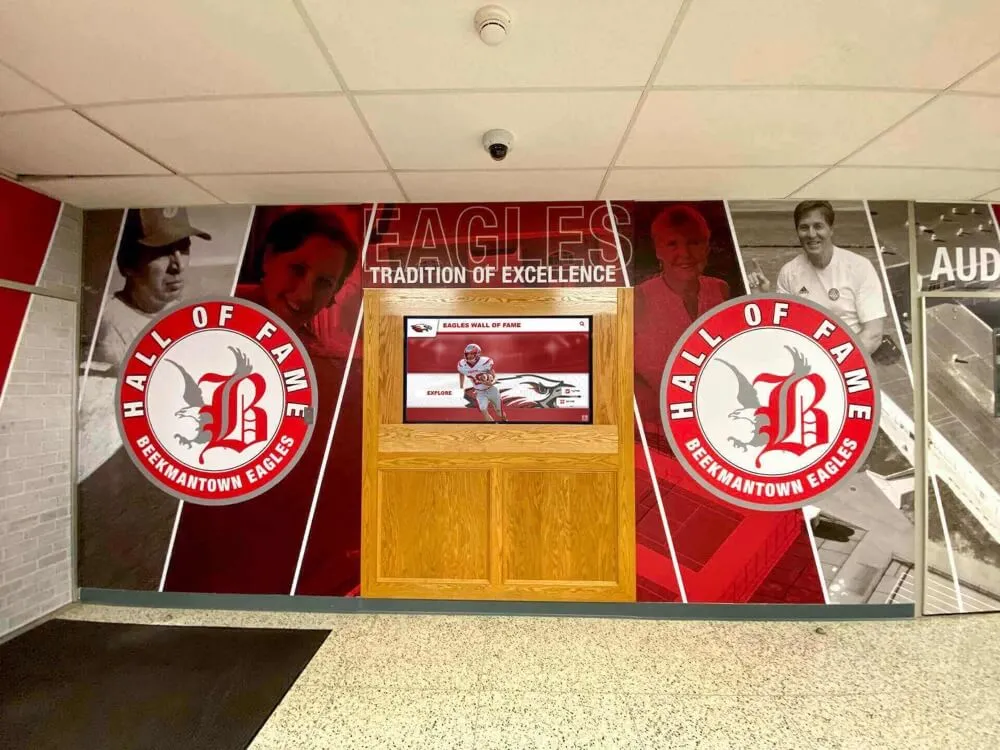
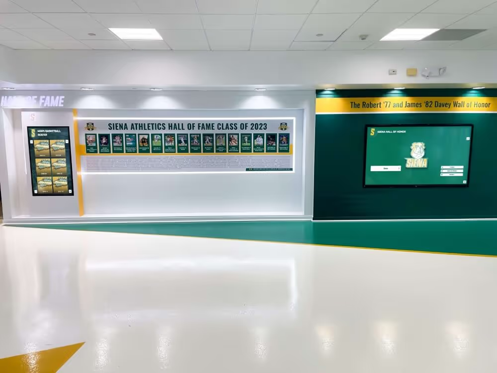
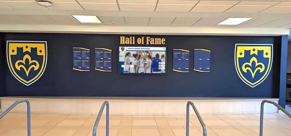
A well-maintained fiber uplink behind a wall of honor display is invisible to visitors — SFP DOM health checks keep it that way by catching optical degradation before it interrupts content delivery at a critical moment
Building an SFP DOM Asset Record for All Recognition Display Uplinks
A DOM asset record stores the baseline values and inspection history for every fiber uplink serving a recognition display switch. It is most useful when maintained alongside the display’s full network documentation: switch port, VLAN assignment, IP address, MAC address, and any special access control configurations such as those tracked during network compatibility testing for recognition platforms.
Recommended fields for a DOM asset record:
| Field | Description | Example |
|---|---|---|
| Display Location | Physical location of the recognition display | Athletic Lobby — Hall of Fame Kiosk |
| Access Switch | Switch the display’s Ethernet cable connects to | SW-IDF-GYM |
| Uplink Interface | SFP port carrying traffic upstream from the access switch | GigabitEthernet1/1/1 |
| Transceiver Model | Vendor and part number of the SFP module | Cisco SFP-GE-L |
| Fiber Type | Single-mode or multi-mode; wavelength | Single-mode, 1310 nm |
| Span Distance | Approximate cable run length | 85 meters |
| DOM Capable | Yes/No | Yes |
| Baseline RX Power | RX power at installation or last clean baseline | −8.7 dBm |
| Baseline TX Power | TX power at installation | −2.4 dBm |
| Baseline Temperature | Temperature at installation | 34.8 °C |
| Last Inspection Date | Date of most recent DOM check | 2026-09-15 |
| Last Inspection RX Power | RX power at most recent check | −9.1 dBm |
| Connector Last Cleaned | Date fiber connectors were last cleaned | 2026-09-15 |
| Notes | Any active warnings, planned maintenance, or historical anomalies | Normal; no warnings |
Maintaining this record for each uplink gives school IT and AV teams a single reference point for every fiber-dependent recognition display in the building. When a display reports a content delivery issue, the first lookup is the DOM asset record — whether the uplink is in normal condition, has an active warning, or is overdue for inspection — rather than a CLI session on an unfamiliar switch.
Schools that extend their recognition programs to include digital hall of fame displays for alumni and community recognition often find that the infrastructure investment in reliable fiber uplinks, documented with DOM baselines and inspection schedules, pays the largest dividend when those displays are in front of visitors who expect them to work without visible IT intervention.
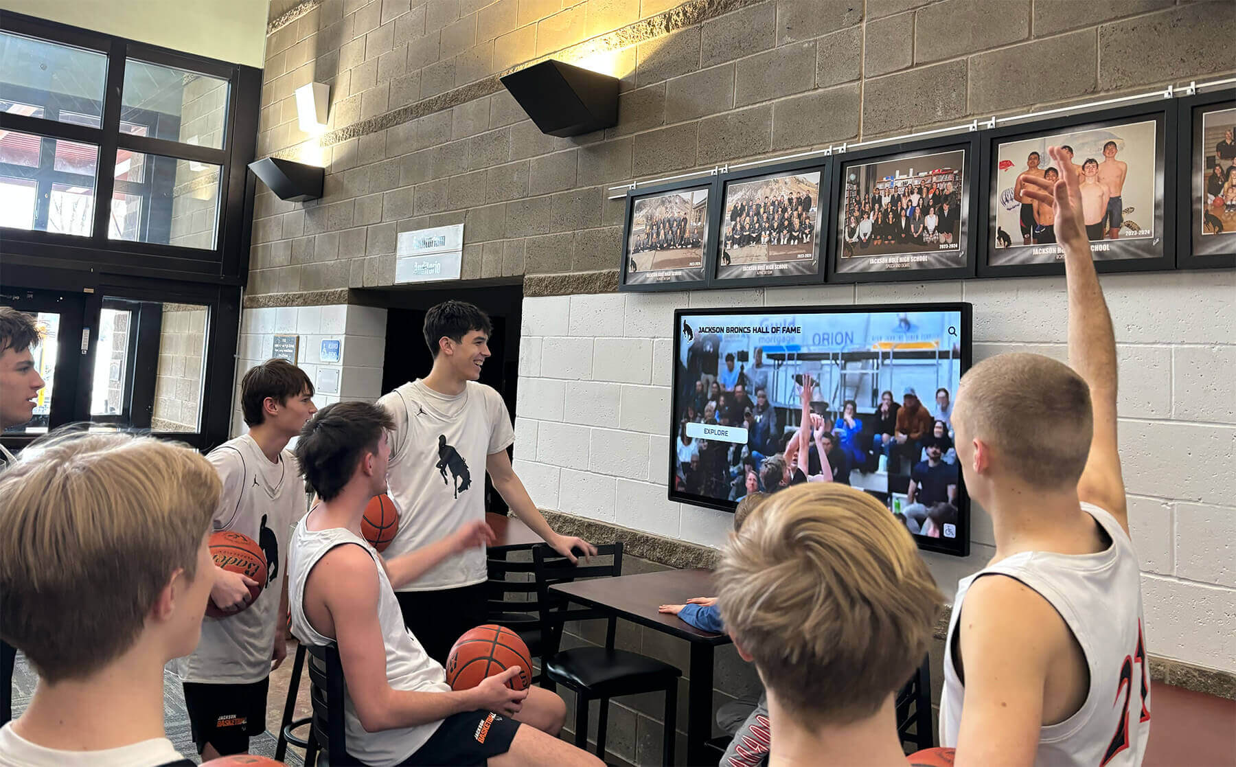
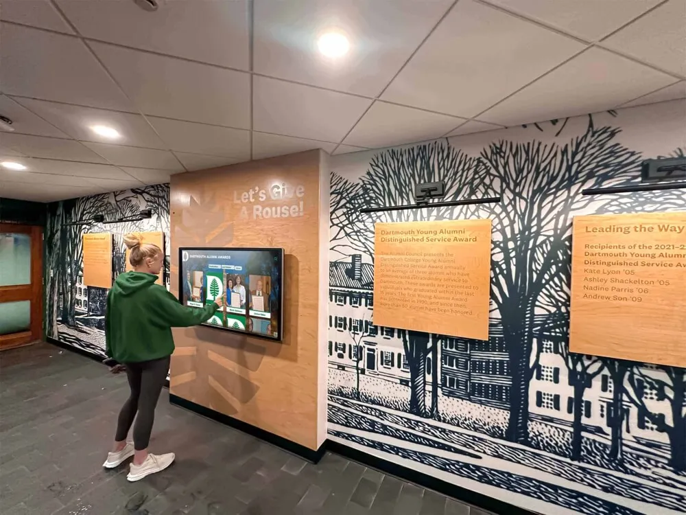
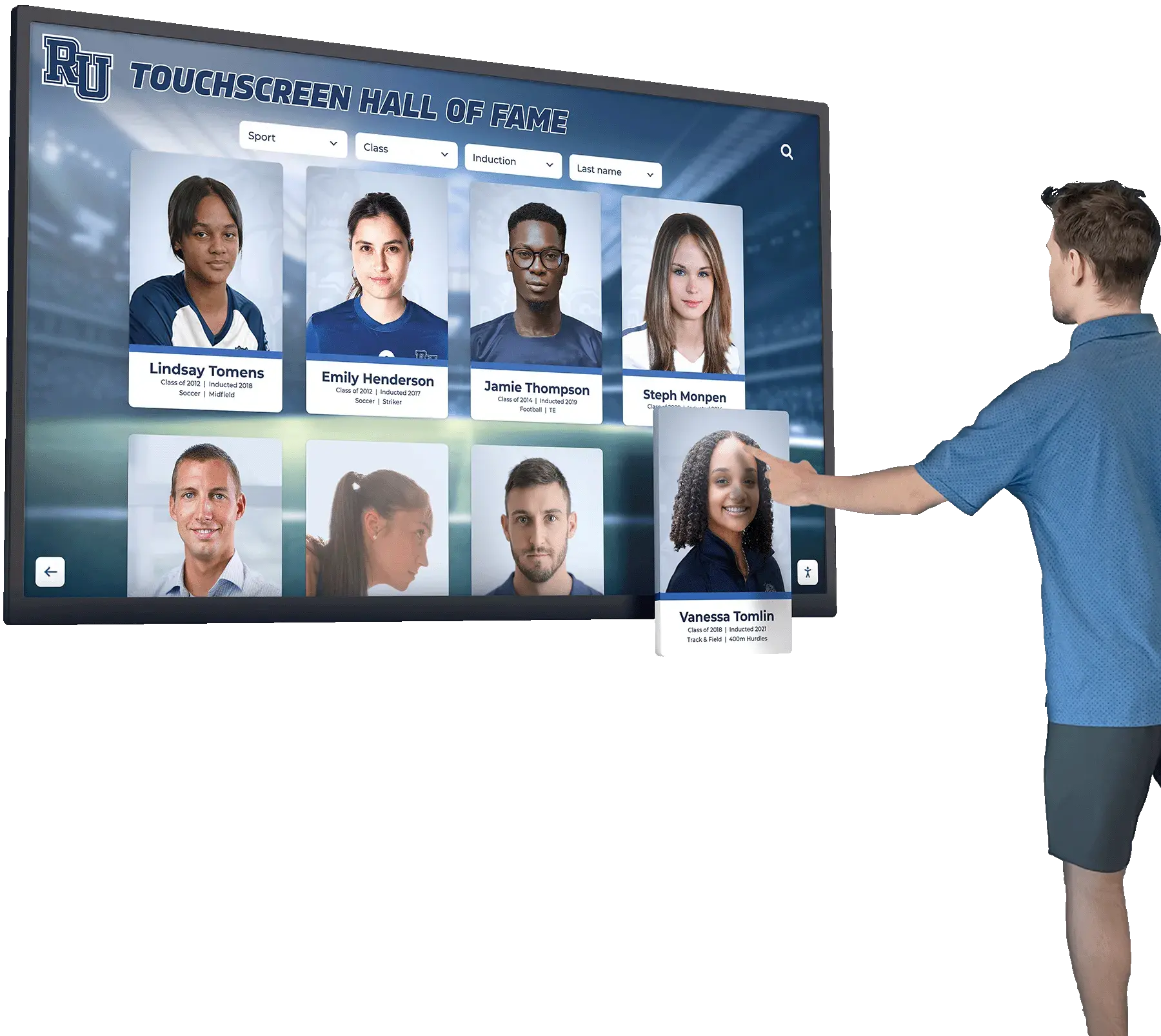
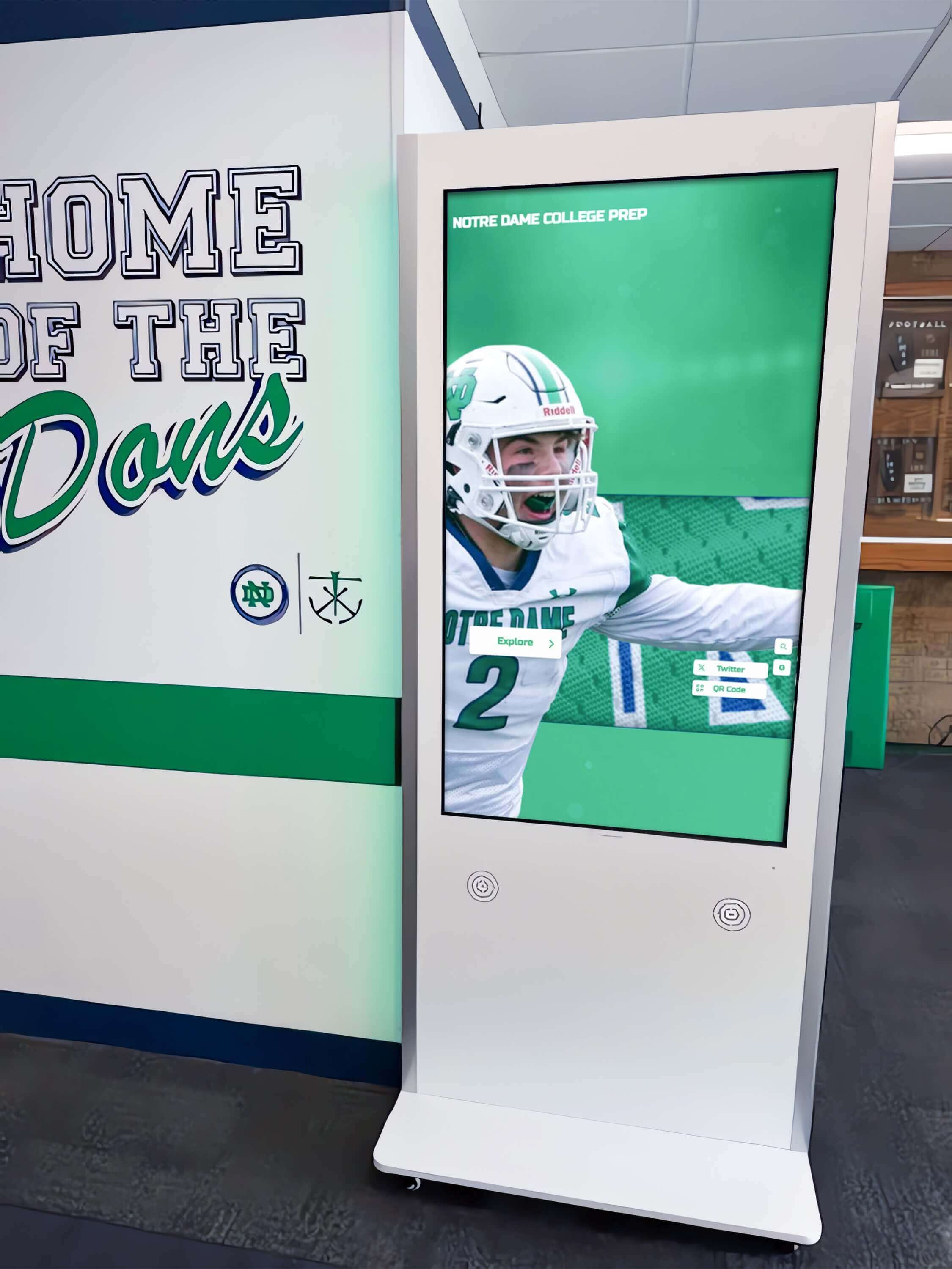
Students engaging with recognition content in real time depend on a fiber uplink that stays within DOM specifications — a marginal RX power reading caught in a quarterly health check prevents the buffering and sync failures that would interrupt this experience
Summary: SFP DOM Health Check Checklist for School Recognition Display Uplinks
Use this checklist before any major recognition event and as a quarterly maintenance procedure.
- Identify all fiber uplinks serving switches that recognition displays connect to — use LLDP neighbor data or cable documentation to confirm the correct interfaces
- Confirm DOM support on each transceiver with
show interfaces transceiver— note any non-DOM modules for planned replacement - Read current DOM values for RX power, TX power, temperature, voltage, and bias current using the appropriate CLI command for your switch vendor
- Check for active warning or alarm flags in the output — any flagged parameter requires investigation before the display is expected to deliver event-day content
- Compare against baseline if a prior baseline exists — look for drift in RX power greater than 2 dBm since the last inspection
- Clean fiber connectors at both ends of any uplink with RX power in the warning range — use a certified fiber end-face cleaner for both the cable connector and the transceiver port
- Re-read DOM values after cleaning — confirm RX power has returned to the normal range
- Replace transceivers or fiber cables if RX power remains at warning or alarm level after cleaning
- Run a content sync load test after any remediation — trigger a full sync from the platform dashboard and confirm completion time is within the expected range
- Update the DOM asset record with current values, the inspection date, and any actions taken
- Schedule the next inspection based on the event calendar — at minimum quarterly, and 48 hours before any major recognition ceremony
Schools that follow this checklist consistently keep their recognition display infrastructure in a known-good state rather than discovering fiber problems during the moments when displays matter most — induction ceremonies, athletics banquets, school board visits, and open-house events where digital trophy cases and hall of fame kiosks are the first impression visitors receive.