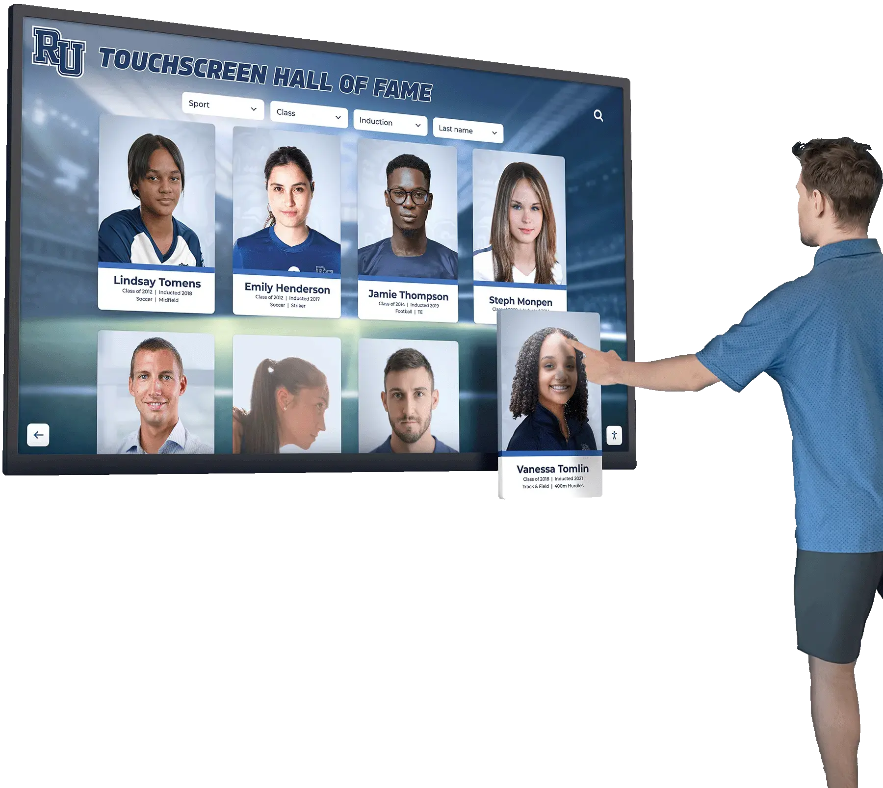



A school recognition display electrical grounding inspection gives facilities coordinators, IT teams, and athletic directors a documented pre-launch process to confirm that the grounding path serving a touchscreen hall of fame, digital award board, or interactive recognition display has been verified before the system goes live in a school environment. Grounding is the foundational layer of electrical safety: it gives fault current a controlled path back to the source, keeps display enclosures at earth potential so a wiring fault does not make the display chassis energized, and ensures that downstream surge protection—however well-specified—actually has a reference point to divert energy toward.
This checklist is not an electrical repair guide, and no item in it authorizes non-licensed personnel to open energized panels, connect or disconnect wiring, or perform any work that requires a licensed electrician under state or local code. Its purpose is to give the facilities and IT team a systematic, documented record-keeping and visual observation framework before a new recognition display is powered on—so that any deficiency requiring licensed remediation is identified, escalated, and resolved before the system enters service.
A complete school recognition display electrical grounding inspection covers six stages: documentation review, visual grounding-path check at the outlet, outlet ground verification with a plug-in tester, display enclosure ground continuity observation, bonding check for wall-mounted display structures, and documentation with escalation routing. Stages one through five are observation and documentation tasks any qualified facilities team member can complete. Any deficiency identified in those stages is escalated to a licensed electrician before the display is connected.

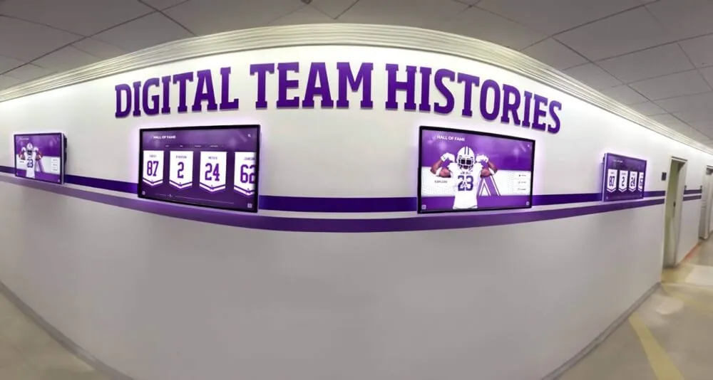
Entrance and lobby recognition displays are among the first things visitors, families, and prospective students see. Completing a grounding inspection before launch ensures the installation is safe, documented, and ready for years of continuous operation.
Why Grounding Verification Matters Before a Recognition Display Goes Live
Electrical grounding is not a post-installation adjustment—it is a condition that must exist before a display is connected. When a recognition display circuit lacks a proper equipment grounding conductor, or when a grounding conductor is present but not properly bonded, several failure modes become possible that do not appear during normal operation until something goes wrong.
Display chassis voltage. A wiring fault—an insulation breakdown, a pinched conductor inside the display enclosure, or a failed internal component—can place line voltage on the metal chassis or mounting hardware of the display. In a properly grounded installation, a grounding conductor carries this fault current and trips the circuit breaker. On an ungrounded circuit, the chassis may sit at a voltage above earth potential without tripping any protective device, presenting a contact hazard to anyone touching the display or its mounting structure.
Surge suppressor ineffectiveness. Every surge protective device (SPD) in the protection stack—whether at the panel, at the branch circuit, or at the point of use—diverts surge energy toward the grounding conductor. An open, reversed, or missing ground wire renders all downstream surge protection partially or entirely ineffective. The display may appear protected (indicator lights may show green on a functioning surge suppressor) while the suppressor has no ground path to divert surge energy through.
Touchscreen false-trigger events and display noise. Equipment grounding also provides a reference voltage for the display’s logic boards and touch sensor circuitry. A floating or high-impedance ground connection can introduce voltage noise that causes touchscreen false triggers, display flicker, or video signal instability. These symptoms are frequently diagnosed as software or configuration problems—and may be resistant to software-based remediation—when their root cause is an inadequate grounding connection.
Schools preparing to launch interactive hall of fame displays and athletic recognition programs in lobby and corridor spaces should include grounding verification in the pre-launch checklist alongside software configuration, content loading, and network connectivity testing.
Scope Boundary: What Facilities Teams Do vs. What Requires a Licensed Electrician
Facilities Team (This Checklist)
- • Gather and review installation documentation
- • Visual observation of outlet, cord, and enclosure ground connections
- • Plug-in outlet tester to verify outlet wiring
- • Continuity observation at display enclosure ground lug
- • Documentation of findings and escalation routing
- • Confirming that licensed electrician work was completed before launch
Licensed Electrician (Required)
- • Opening or inspecting inside electrical panels
- • Adding, moving, or confirming grounding conductors in conduit
- • Installing, replacing, or testing grounding electrode systems
- • Measuring bonding conductor resistance or impedance
- • Any work on energized wiring or panel components
- • Correcting any grounding deficiency found during inspection
Stage 1 — Documentation Review
Before any physical inspection, the facilities team should gather and review the electrical documentation associated with the circuit serving the recognition display. This stage establishes whether an inspection can proceed or whether licensed electrician involvement is required before the facility team starts.
Documentation Review Checklist
- ☐Obtain the electrical permit and inspection records for the circuit serving the recognition display. New recognition display installations in school buildings typically require an electrical permit when new circuits are pulled or existing circuits are modified. Confirm that a permit was obtained, work was completed by a licensed electrician, and the circuit passed final inspection by the authority having jurisdiction (AHJ). If permit records are unavailable, escalate to a licensed electrician before proceeding with this checklist.
- ☐Confirm the circuit is designated in the building's panel schedule and labeled at the panel. The panel schedule should list the circuit breaker number, amperage, circuit description, and the location served. If the recognition display circuit is not listed or is listed as a general-purpose circuit shared with other loads, document this finding and route it to the facilities manager before the display is connected.
- ☐Review the display vendor's installation guide for grounding requirements. Commercial recognition display manufacturers specify grounding requirements in their installation documentation. This may include a three-wire grounded outlet with a specified amperage rating, a requirement for a dedicated circuit, or grounding specifications for the display mounting hardware. Collect this documentation before inspection and confirm the installed circuit meets it.
- ☐Verify the building's electrical system age and relevant upgrade history. School buildings constructed before the mid-1960s may contain wiring systems where equipment grounding conductors were not required on branch circuits under applicable codes at the time of construction. If the building has pre-1965 wiring that has not been updated, escalate to a licensed electrician before installing any recognition display equipment. Older wiring does not necessarily preclude display installation—but it does require a licensed assessment before connection.
- ☐Obtain the display installation diagram showing cable routing from panel to outlet to display. This diagram is the reference point for the visual inspection in Stage 2. If no as-built diagram exists, create one during this inspection by tracing the visible installation and documenting conduit paths, outlet locations, and cable routing.
Stage 2 — Visual Inspection of the Grounding Path at the Outlet
The outlet serving the recognition display is the accessible endpoint of the branch circuit’s grounding system. A trained facilities observer can assess several grounding-relevant conditions at the outlet without opening the electrical system.
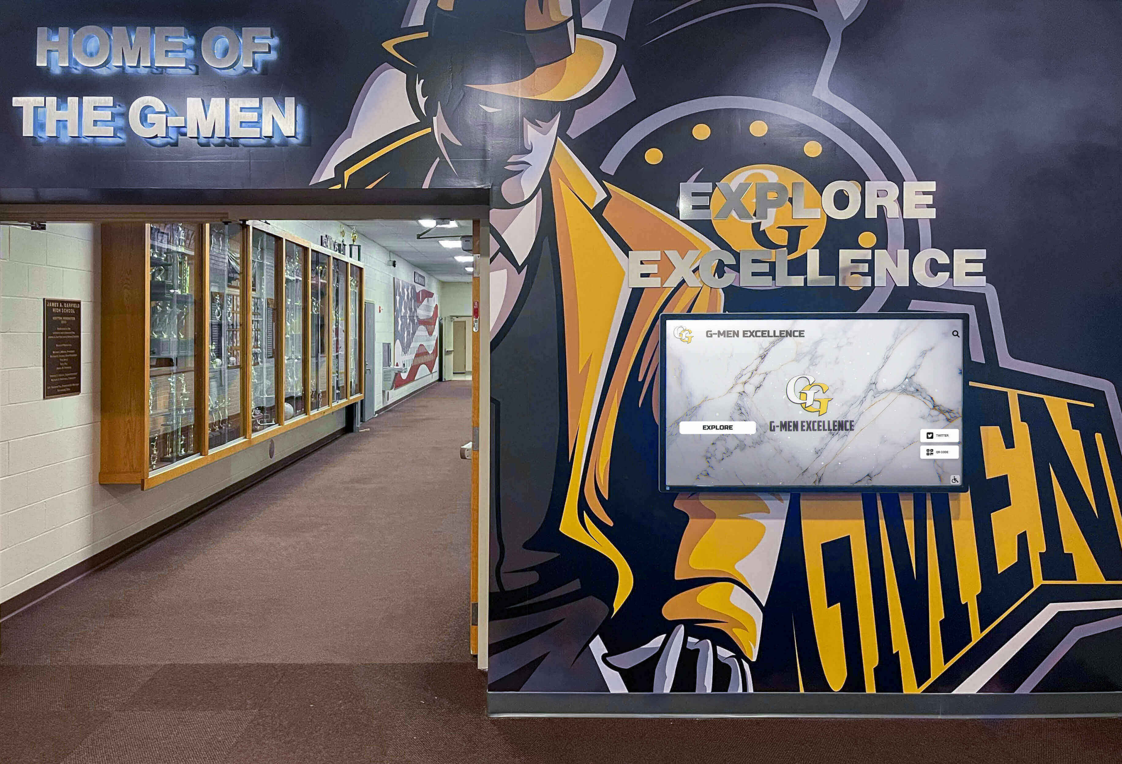
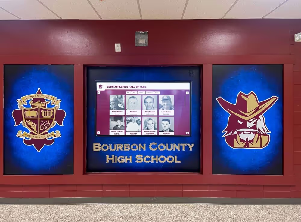
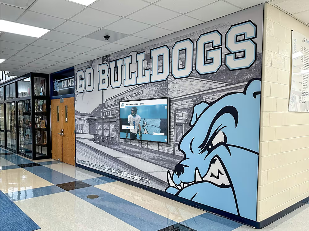
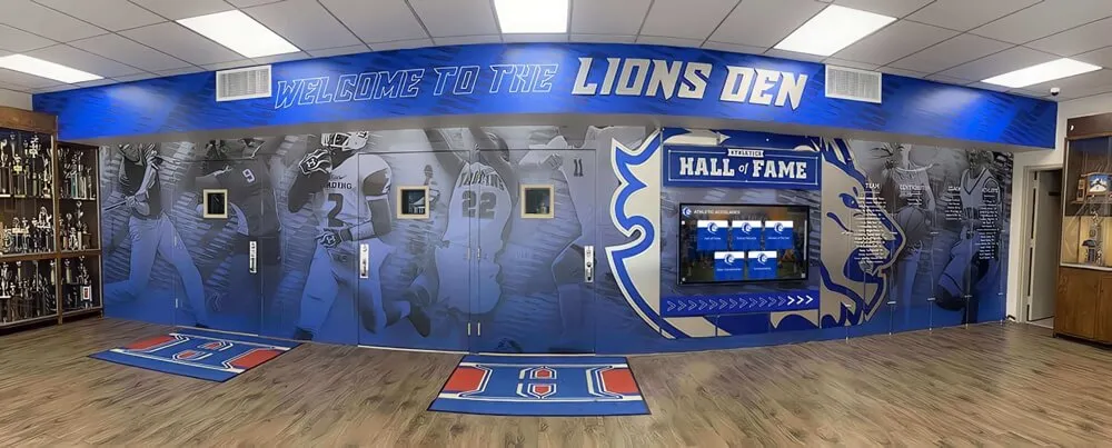
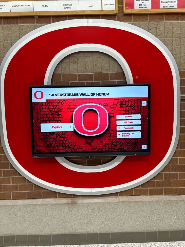
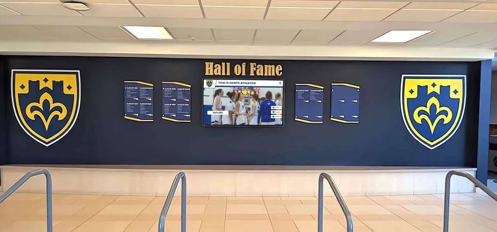
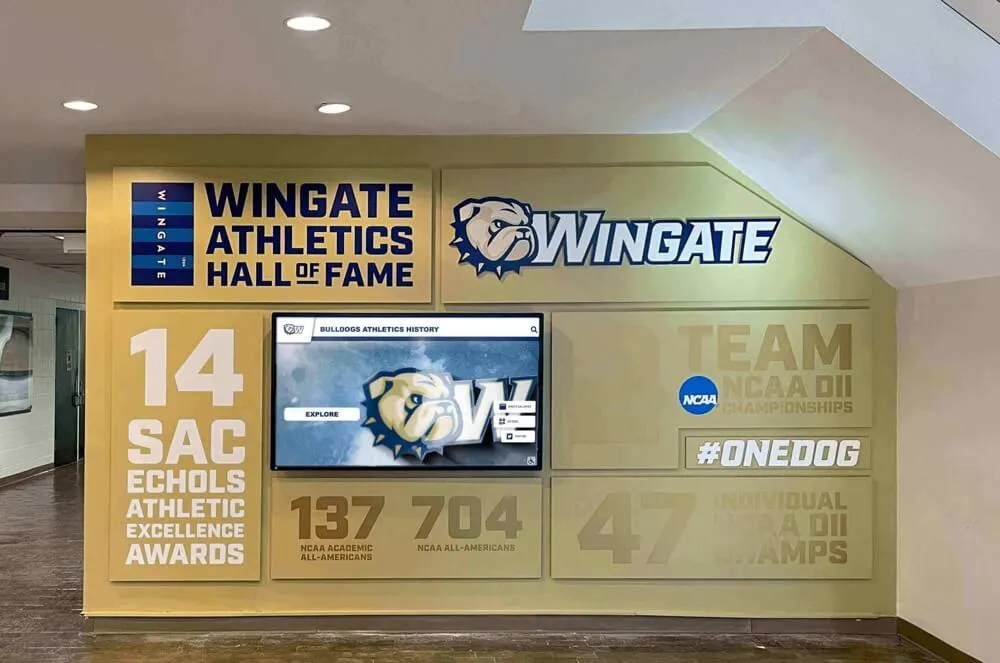
Recognition displays adjacent to trophy cases and athletic murals are typically installed in high-traffic corridors — verifying the grounding path at the serving outlet establishes a safety foundation before the display is powered on.
Outlet Visual Inspection Checklist
- ☐Confirm the outlet is a three-prong (NEMA 5-15R or 5-20R) grounded outlet, not a two-prong ungrounded outlet. A two-prong outlet indicates the circuit either lacks an equipment grounding conductor or has an older installation where grounded outlets were not required. Do not use an ungrounded-to-grounded adapter ("cheater plug") on a recognition display installation. Route this finding to a licensed electrician for evaluation and correction.
- ☐Inspect the outlet face and cover plate for discoloration, cracking, or evidence of heat exposure. Scorch marks, discoloration of the outlet face around plug slots, or a cover plate that is cracked or melted indicate a prior overload or arcing event. Remove the display from this circuit's consideration and request a licensed electrician evaluation before any equipment is connected.
- ☐Confirm the outlet cover plate is flush with the wall and that the outlet box is secure. A loose outlet box—detectable when the outlet moves in its wall opening when you apply finger pressure to the cover plate—can indicate loose conductors inside the box, including the grounding conductor. Document any outlet movement and route it to facilities maintenance for correction by a licensed electrician before the display is connected.
- ☐Verify that the outlet is accessible for the recognition display's power cord without requiring an extension cord. Extension cords are not a permitted permanent wiring method for commercial equipment installations. If the outlet location requires an extension cord to reach the display's power inlet, document this as a wiring deficiency requiring a licensed electrician to install an outlet in the correct location before launch.
- ☐Confirm the outlet is on a dedicated circuit, not shared with HVAC controls, gymnasium equipment, or copiers. Shared circuits increase transient voltage exposure. Verify dedication by confirming the circuit breaker at the panel serves only the display outlet—a licensed electrician or qualified facilities electrician can confirm this with a simple breaker-to-outlet trace.
Stage 3 — Outlet Ground Verification with a Plug-In Tester
A three-light plug-in outlet tester is the appropriate non-invasive tool for verifying outlet wiring conditions at a recognition display circuit. These devices are sold at hardware and electrical supply stores and provide an immediate indication of common wiring faults without requiring opening the outlet box or the electrical panel.
Plug-In Tester Checklist
- ☐Use a UL-listed three-light plug-in outlet tester—not a multimeter or improvised test device. Plug-in testers are designed for safe use by non-licensed personnel at outlets under normal operating conditions. They indicate the most common outlet wiring faults—open ground, open neutral, open hot, reversed hot/neutral, reversed hot/ground—through a standardized light pattern printed on the device. Read the light pattern against the legend on the device and confirm the result matches the "correct wiring" pattern before proceeding.
- ☐A pattern indicating "open ground" requires immediate escalation to a licensed electrician. An open ground means the grounding conductor at this outlet is either absent, broken, or disconnected. Connect no recognition display equipment to this outlet until the deficiency is corrected and re-verified. Document the tester result, the outlet location, and the date of the finding in the pre-launch inspection record.
- ☐A pattern indicating "reversed hot/ground" requires immediate escalation and display removal from this circuit. A hot/ground reversal places line voltage on the grounding conductor—a serious wiring error that requires licensed electrician correction. This condition places voltage on circuit paths intended to be at earth potential, including surge suppressor ground terminals and display enclosure chassis grounds. Do not connect any equipment to an outlet showing this indication.
- ☐A pattern indicating "correct wiring" passes Stage 3 for this outlet. Document the tester model, the outlet location, the test result, and the date. Retain this documentation in the pre-launch inspection record as evidence of ground verification. Note that a correct-wiring tester result confirms the outlet wiring is properly connected but does not verify the quality of the grounding electrode system—that assessment requires licensed electrician measurement.
- ☐Test each outlet to which recognition display equipment will be connected, not only the primary display outlet. Media players, network switches, and auxiliary audio or lighting equipment connected to the recognition display installation may plug into separate outlets. Each outlet serving these devices should pass the plug-in tester check before equipment is connected. An open ground at a media player outlet presents the same risks as an open ground at the display outlet itself.
| Tester Light Pattern | Indicated Condition | Required Action Before Display Connection |
|---|---|---|
| Correct wiring | Outlet wired correctly; ground conductor connected | Document result; proceed to Stage 4 |
| Open ground | Grounding conductor absent or disconnected | Do not connect equipment; escalate to licensed electrician |
| Open neutral | Neutral conductor absent or disconnected | Do not connect equipment; escalate to licensed electrician |
| Open hot (no lights) | Hot conductor absent; circuit not energized | Confirm breaker is on; if on, escalate to licensed electrician |
| Reversed hot/neutral | Hot and neutral conductors reversed at outlet | Do not connect equipment; escalate to licensed electrician |
| Reversed hot/ground | Hot conductor connected to ground terminal — serious fault | Do not connect equipment; escalate to licensed electrician immediately |
Schools that have built substantial alumni recognition and award archive programs into their recognition displays should treat this tester check as a prerequisite—not a bureaucratic step—before the display system carrying that institutional history is powered on for the first time.
Stage 4 — Display Enclosure Ground Continuity Observation
Modern commercial recognition displays include an equipment grounding terminal or lug on the display enclosure—a point where the building’s equipment grounding conductor can be bonded to the metal housing of the display. This is distinct from the outlet grounding pin and provides a direct path for fault current if a wiring failure occurs inside the display enclosure itself.
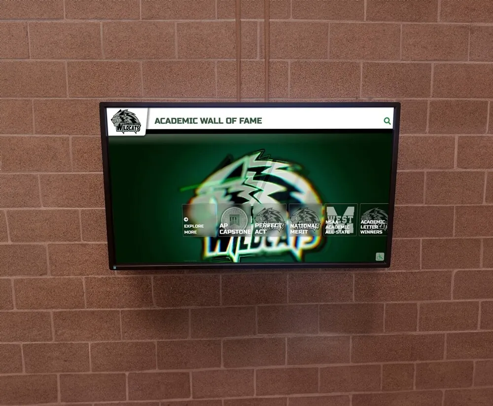
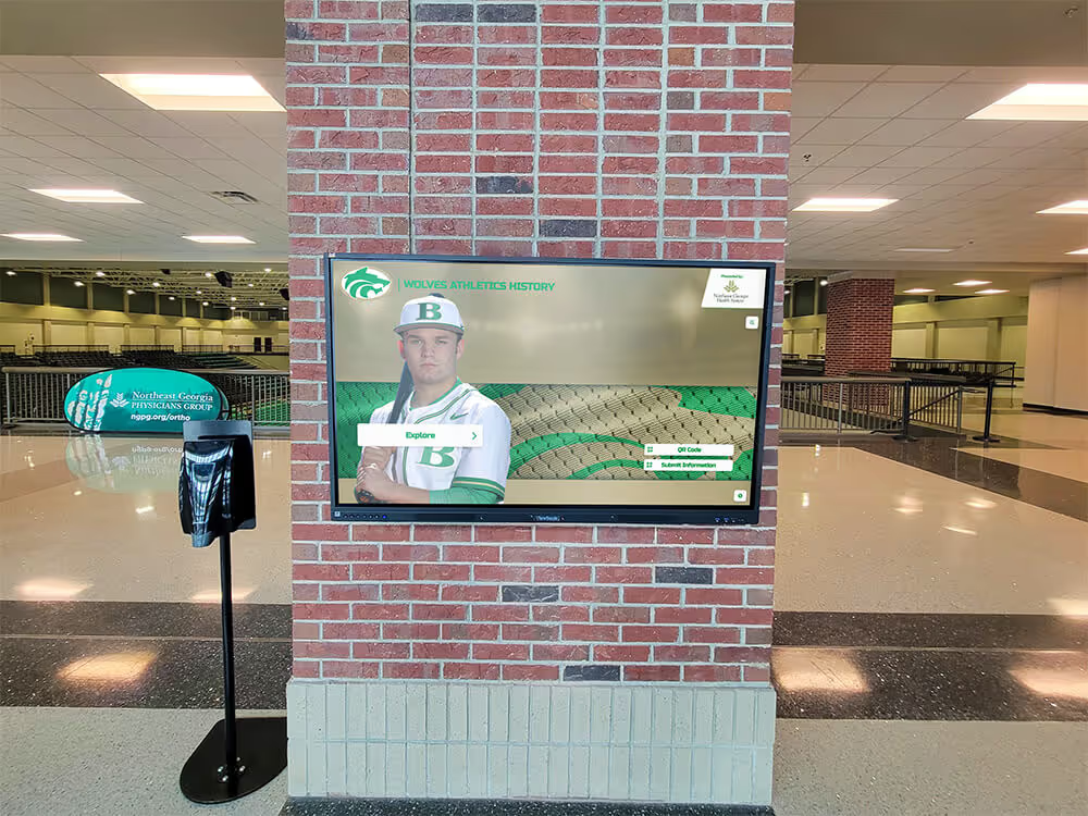
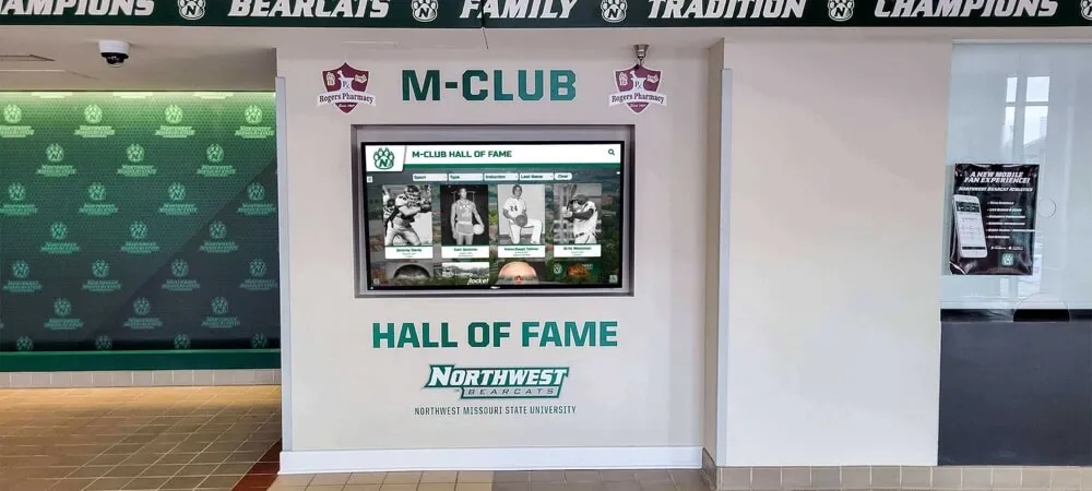
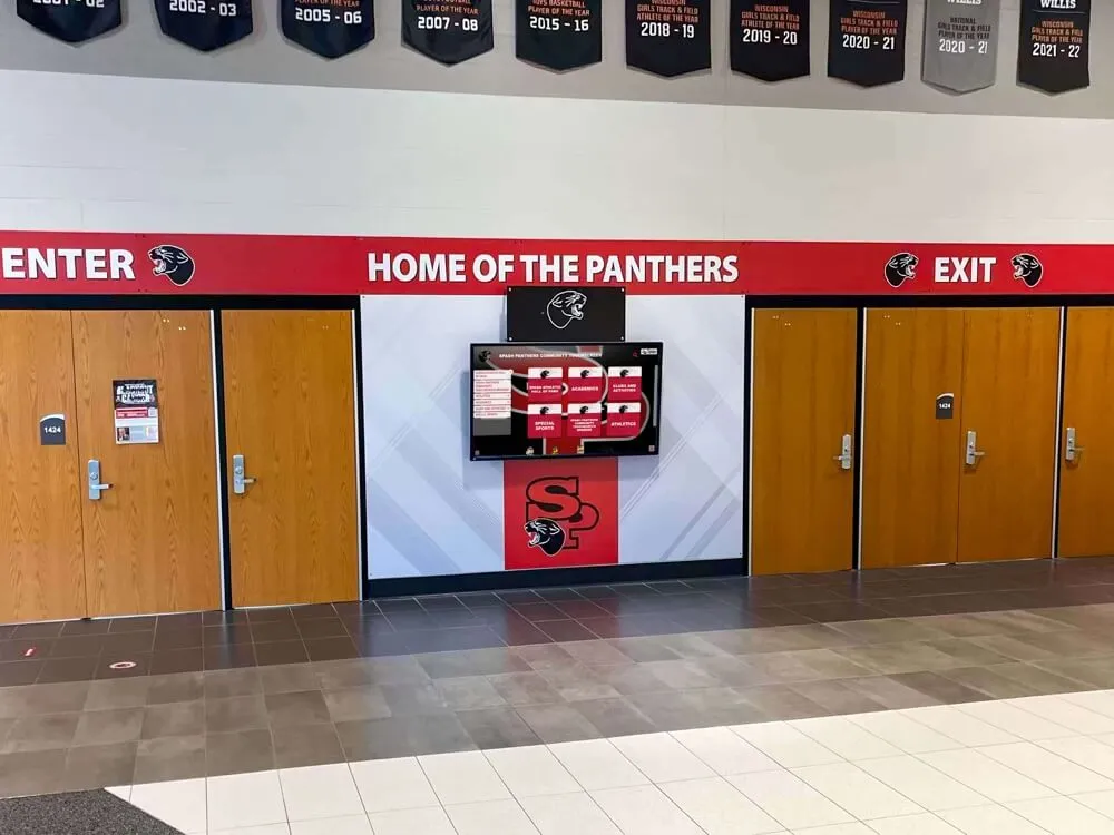
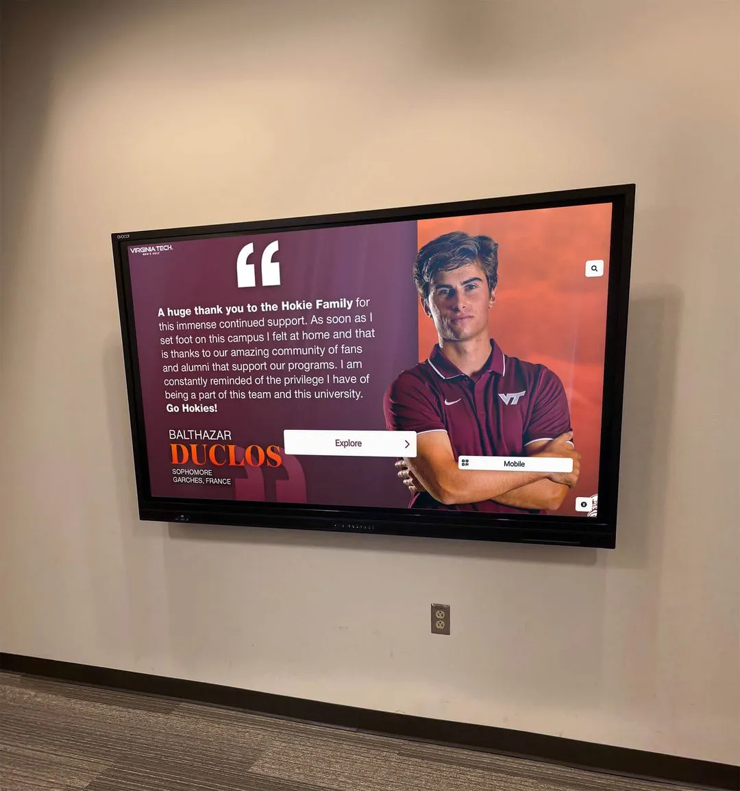
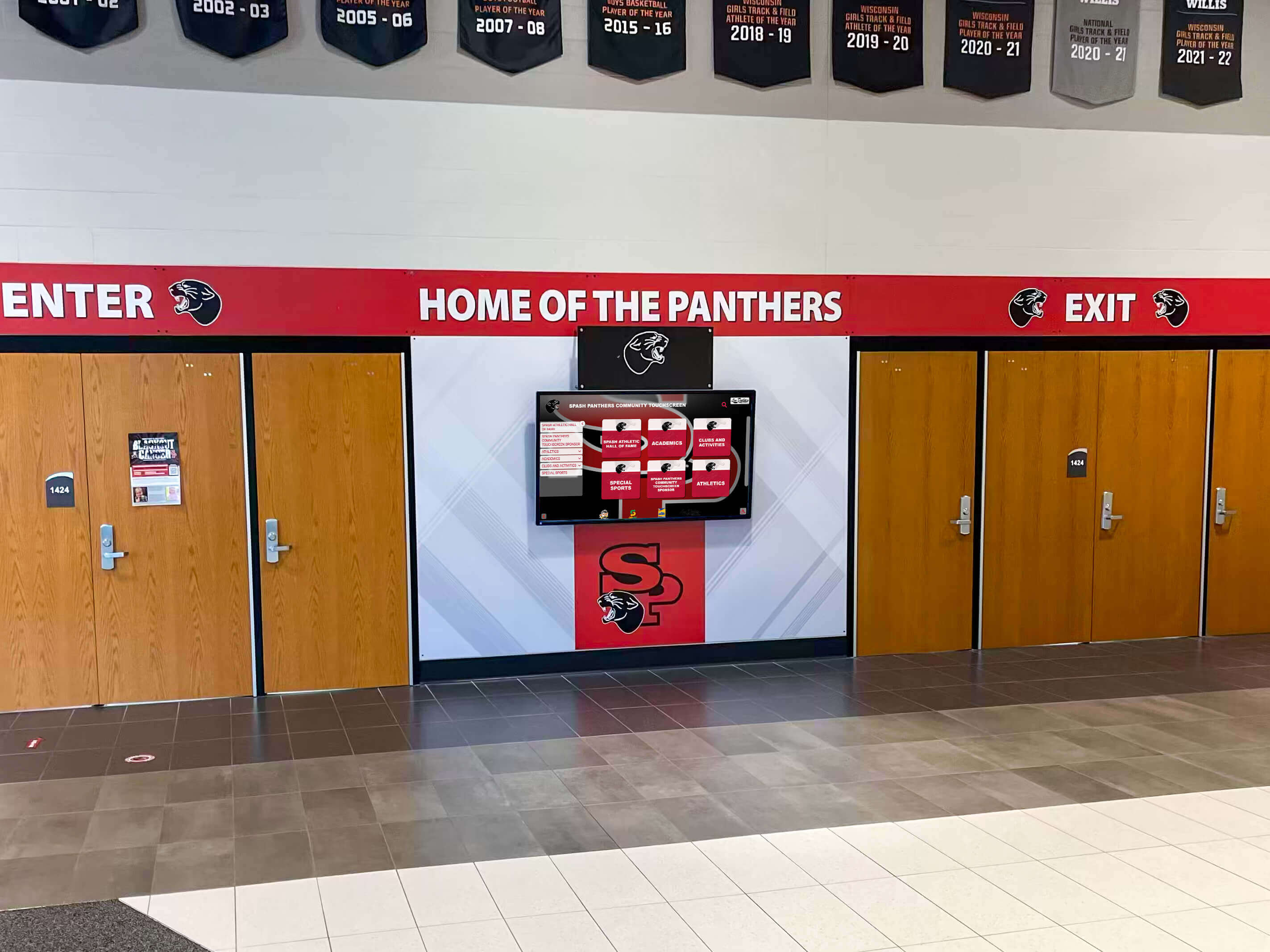
Wall-mounted recognition displays with metal enclosures require a verified connection between the enclosure chassis and the building's equipment grounding system — this provides the fault current path that a circuit breaker needs to operate correctly in a wiring fault scenario.
Enclosure Ground Observation Checklist
- ☐Locate the equipment grounding terminal or lug on the display enclosure as specified in the manufacturer's installation documentation. Most commercial display enclosures include a labeled grounding terminal—often a green screw, a marked lug, or a chassis bonding point identified in the installation guide. Confirm this terminal is accessible, visible, and identified before the display is mounted in its final position. Post-mounting access to the grounding terminal may require removing mounting hardware in some installation configurations.
- ☐Verify that a grounding conductor is attached to the enclosure terminal and is connected to a grounded point in the installation. In most recognition display installations, this connection is made through the grounded power cord—the ground pin of the power plug connects through the outlet and branch circuit wiring back to the panel's grounding bus. In installations using a direct-wired power connection or a custom enclosure, confirm with the installing electrician that a separate grounding conductor has been provided from the enclosure terminal to a grounded point.
- ☐Inspect the grounding conductor connection at the enclosure terminal for visible security and conductor integrity. The grounding conductor should be attached with a secure lug or screw connection—not wrapped around a screw, not held with electrical tape, and not simply lying against the chassis without a mechanical connection. Visible corrosion on the grounding terminal or conductor, broken conductor strands at the terminal, or a loose connection are grounds for escalation to the installing electrician before launch.
- ☐For rack-mounted media players and auxiliary equipment, confirm that rack grounding is addressed in the installation design. Equipment rack installations used to house recognition display media players and control systems should be grounded as a system. Confirm with the installing electrician or AV installer that the rack's grounding is specified and implemented—rack grounding is a separate requirement from individual device power cord grounding in installations where the rack itself is a metal enclosure.
- ☐Note any grounding conductors routed in a way that could be damaged by display mounting hardware, cable management, or routine access. A grounding conductor that passes through a sharp-edged knockout, is compressed under a cable tie, or is routed across a moving panel that could pinch the conductor is at risk of damage over time. Flag any such routing for correction by the electrician before launch.
Stage 5 — Bonding Check for Wall-Mounted Display Structures
Recognition displays mounted on metal framing, unistrut rails, or custom wall brackets introduce an additional grounding consideration: the metal mounting structure itself. Metal structures physically connected to the display enclosure or to conduit carrying the display circuit should be bonded to the equipment grounding system.
Mounting Structure Bonding Checklist
- ☐Identify all metal components of the display mounting system: brackets, rails, unistrut channels, back-plates, and any metal panel or frame that forms part of the installation. These components should be listed in the as-built installation documentation. If no documentation exists, visually trace every metal structural element associated with the display and record each component as part of the inspection record.
- ☐Confirm with the installing electrician whether each metal mounting component has been bonded to the equipment grounding system. This is an installer responsibility that the facilities observer verifies by reviewing the installation documentation and asking the electrician directly. A bonding jumper—a conductor connecting the metal structure to the display circuit's grounding conductor or to the building's grounding system—should be noted in the installation record.
- ☐Visually inspect metal conduit connections along the cable pathway from the panel to the display outlet. Metal conduit used to protect branch circuit wiring also serves as an equipment grounding path when properly connected. Confirm that conduit fittings are fully threaded into outlet boxes and panel knockouts—a fitting that is partially threaded or cross-threaded may not maintain adequate ground continuity over time. Escalate any damaged or incomplete conduit connections to a licensed electrician.
- ☐Confirm that isolated metallic components—VESA mounting plates, decorative surrounds, or sponsor panel frames—are not inadvertently connected to the display enclosure without a grounding path. A decorative metal panel bolted to a display enclosure with no grounding conductor can present the same chassis-voltage risk as an ungrounded enclosure if the display has an internal fault. These cosmetic components are sometimes added by facilities staff or AV integrators after the electrical work is complete; verify that any added metalwork is included in the grounding assessment.
- ☐For displays mounted on exterior or semi-exterior walls, confirm with the licensed electrician that lightning exposure is addressed in the grounding design. Displays installed near building entrances, under canopies, or on walls adjacent to athletic fields may require additional bonding provisions if the building has a lightning protection system. This assessment requires licensed electrician input and is beyond the scope of the facilities observation, but the facilities team should confirm that it was addressed in the installation design review.
Schools investing in interactive recognition displays for campus storytelling and community engagement often mount displays in high-visibility lobby and entrance locations where metal structural elements—door frames, architectural panels, and display surrounds—are part of the installation design. Ensuring these elements are included in the grounding assessment prevents a gap that appears years later when a maintenance event exposes a bonding deficiency.
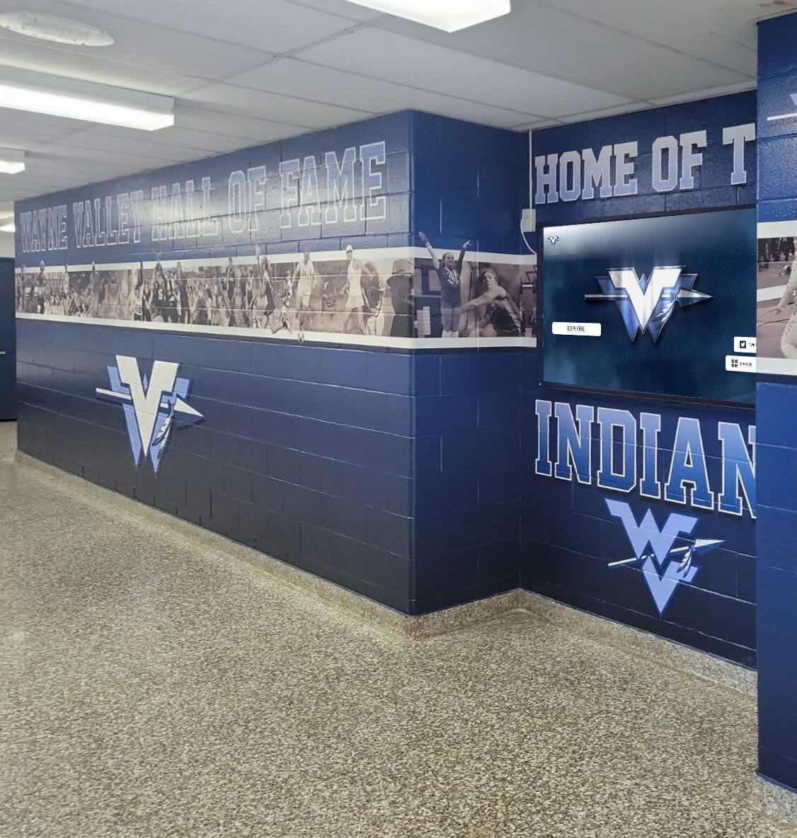
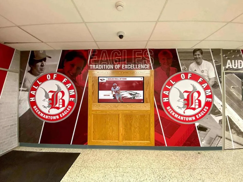
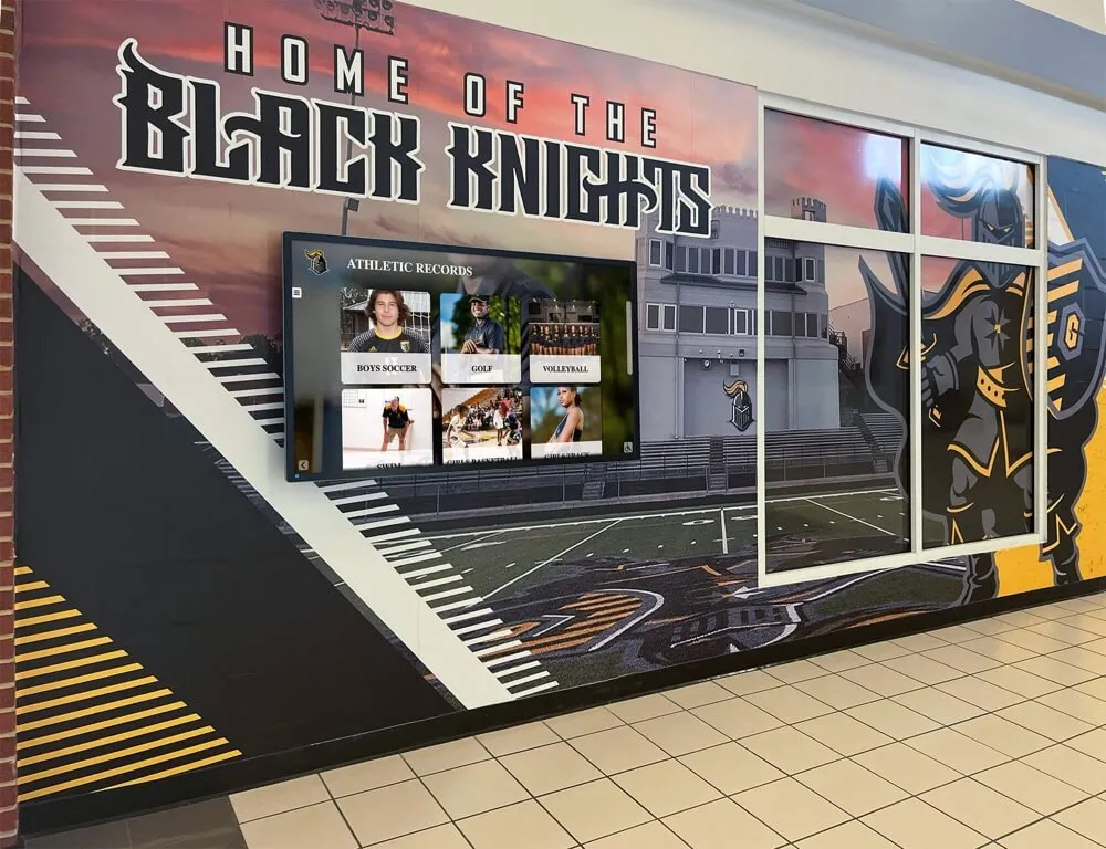
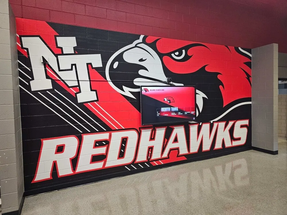
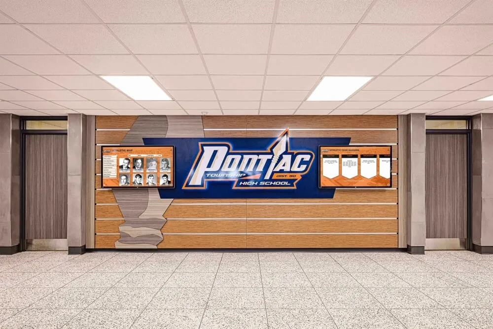
Recognition displays integrated into hallway murals and branded wall installations often involve metal framing elements — the pre-launch grounding inspection should identify every metal component connected to the display structure and confirm each is addressed in the electrician's grounding design.
Ready to Plan a Recognition Display Installation That Starts Right?
Rocket Alumni Solutions works with school athletic directors, facilities teams, and IT coordinators on recognition display projects from site assessment through long-term platform support. See how a properly installed, cloud-managed recognition display could transform your school's athletic legacy presentation.
Request a DemoStage 6 — Documentation and Escalation Routing
A grounding inspection that produces no written record provides no lasting protection and no evidence of due diligence for insurance, warranty, or liability purposes. Every finding at each stage should be documented before the inspection team leaves the installation location.
Documentation and Escalation Checklist
- ☐Complete a pre-launch inspection form for each recognition display location. The form should record: display location and identifier, circuit breaker number and panel location, outlet tester result and tester model, outcome of each Stage 1 through Stage 5 checklist item, any findings requiring escalation, date of inspection, and names of inspection team members. Store completed forms in the recognition display's facilities file.
- ☐Photograph the outlet tester reading, the enclosure ground terminal, and any finding requiring escalation. Photographs date-stamp findings, provide evidence that the inspection was completed, and give the escalated electrician a clear visual reference without requiring a separate site visit to understand the deficiency. Label each photograph with the display location and the checklist stage it documents.
- ☐Classify every finding using a three-tier escalation priority.
Hold: Any Stage 3 tester result other than "correct wiring," any visible enclosure grounding deficiency, or any unresolved documentation gap. Display must not be connected until the finding is resolved by a licensed electrician and re-verified.
Pre-launch correction: Any finding that a licensed electrician can correct before the launch date—conduit fitting tightness, bonding jumper for an added metalwork component, documentation gap requiring permit follow-up.
Document and monitor: Findings that do not pose an immediate safety concern but should be addressed in the next maintenance cycle—improved outlet labeling, documentation updates, or access improvements for future inspection. - ☐Route Hold-classified findings to the facilities manager and the licensed electrician of record immediately. Include the inspection photo, the specific checklist item that generated the finding, and the requested resolution before the display is energized. Do not connect the display or apply power to the circuit serving it until the licensed electrician has completed the correction and provided written confirmation.
- ☐Obtain written sign-off from the licensed electrician of record before the display goes live. The electrician's confirmation should state that all escalated findings have been corrected and that the circuit, outlet, and enclosure grounding have been verified to meet applicable code requirements. Attach this confirmation to the pre-launch inspection record. This documentation supports the display vendor's warranty, the school's insurance coverage for the installation, and the facilities team's record of due diligence.
- ☐Schedule the first annual re-inspection and add it to the facilities calendar before the display goes live. The pre-launch inspection establishes a baseline. An annual re-inspection—most practical in August before the school year begins—confirms the grounding path remains intact after a year of operation, building renovation activity, and any maintenance access to the display or its circuit.
Responsibility Table: Grounding Inspection Roles
Clear role assignment prevents the common gap in which the facilities team assumes the IT coordinator has verified the power installation and the IT coordinator assumes the facilities team has handled it.
| Inspection Stage | Primary Owner | Support Role | Escalation Path |
|---|---|---|---|
| Stage 1: Documentation review | Facilities coordinator | IT coordinator, athletic director | Licensed electrician if permit records missing |
| Stage 2: Outlet visual inspection | Facilities coordinator | IT coordinator | Licensed electrician for any observed damage or box movement |
| Stage 3: Plug-in tester check | IT coordinator or facilities | Facilities coordinator | Licensed electrician for any result other than correct wiring |
| Stage 4: Enclosure ground observation | IT coordinator | Facilities coordinator | Installing electrician for any observed deficiency |
| Stage 5: Mounting structure bonding | Facilities coordinator | Installing electrician (confirmation) | Licensed electrician for any unaddressed metalwork |
| Stage 6: Documentation and escalation | Facilities coordinator | IT coordinator, athletic director | Facilities manager for Hold-classified findings |
| Deficiency correction | Licensed electrician | Facilities coordinator (access) | Authority having jurisdiction (AHJ) if permit required |
| Pre-launch sign-off | Licensed electrician (written) | Facilities manager | Do not launch without written electrician sign-off |
Schools coordinating booster club oversight of recognition display investments should share a summary of the pre-launch inspection outcome with booster leadership. When booster funds contributed to the display installation, booster leadership has an interest in confirmation that the installation was completed to standard. A completed and signed pre-launch inspection form provides that confirmation without requiring booster representatives to evaluate technical specifications themselves.
Grounding Inspection for Multi-Display Installations
Schools adding multiple recognition displays—a digital hall of fame in the gymnasium lobby, an academic honor board in the main corridor, and a donor recognition display near the auditorium—should treat each display location as an independent pre-launch inspection with its own documentation. Grounding conditions vary by location: an outlet in the gymnasium lobby may be on a different panel, served by different conduit, and have different grounding history than an outlet in the main corridor.
For multi-display campuses, extend the pre-launch process to include:
- A campus grounding inspection log that records Stage 3 tester results and Stage 6 sign-off status for every display location, organized by panel and circuit number
- A consolidated status board showing which display locations have passed all six stages and which have open Hold items requiring electrician resolution
- A shared launch calendar that defers activation of any display with an open Hold classification until all findings are resolved and the licensed electrician’s written sign-off is obtained
- A recurring annual re-inspection schedule that staggers inspections across display locations rather than attempting to inspect all locations in a single week
Schools planning to expand their recognition program to additional locations—adding a sport-specific FBLA or FFA award display or trophy and plaque recognition wall—should add a pre-launch grounding inspection to the procurement timeline for each new location, not as an afterthought after hardware is installed.

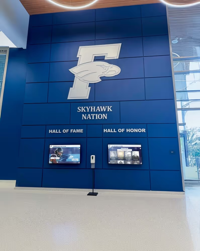
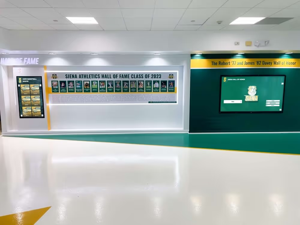
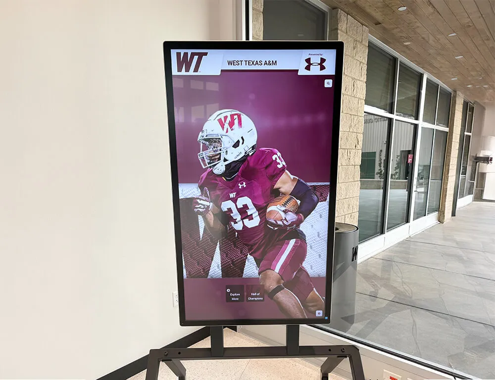
Multi-display recognition installations in school lobbies involve multiple outlets, circuits, and mounting structures — each display location requires its own documentation, tester check, and licensed electrician sign-off before that specific display is energized.
Escalation Triggers: When to Stop and Call a Licensed Electrician
Some findings during the six-stage inspection require stopping immediately and routing to a licensed electrician before any further steps are taken. The facilities team should not attempt to correct these findings independently.
Stop and Escalate: Conditions That Require a Licensed Electrician Before Proceeding
- →Any plug-in outlet tester result other than "correct wiring." Open ground, open neutral, reversed conductors, or open hot all indicate a wiring deficiency that requires a licensed electrician to diagnose and correct inside the outlet box or at the panel. Do not connect any equipment to the circuit until the electrician has corrected the deficiency and the tester confirms correct wiring.
- →Scorch marks, discoloration, or deformation at the outlet face, plug blades, or power cord terminals. These indicate a prior heat event caused by arcing, overloading, or a high-resistance connection. The outlet and potentially the circuit wiring require electrician evaluation before the display is connected.
- →A two-prong ungrounded outlet at any display connection point. Installing a grounding adapter is not an acceptable correction. A licensed electrician must evaluate the circuit and provide a compliant grounded outlet using a method acceptable under applicable code.
- →Missing electrical permit records for new circuits or outlet additions. If new wiring was installed for the recognition display without a permit, or if permit records cannot be located, a licensed electrician and the authority having jurisdiction should review the installation before the display is connected. Unpermitted work may not meet current code requirements for grounding conductor sizing or bonding.
- →A loose outlet box that moves when finger pressure is applied to the cover plate. Outlet box movement can indicate loose internal conductors, including the grounding conductor. Do not energize the outlet until a licensed electrician opens and inspects the box.
- →Visible damage to the grounding conductor at the display enclosure terminal. Broken strands, corrosion, or a visibly loose connection at the enclosure's grounding lug requires the installing electrician to correct the connection. A grounding conductor that is not securely terminated provides little or no fault protection.
Connecting Grounding Inspection to Recognition Program Reliability
The case for completing a grounding inspection before a recognition display goes live is not only about electrical safety—though safety is the primary reason. It is also about protecting the recognition program itself.
A display that goes offline due to a fault triggered by an improperly grounded circuit fails the school’s recognition mission at precisely the moment that mission is most visible: during a hall of fame induction, a homecoming week, or a public event when families and community members expect the display to be running. The fault may be intermittent—the display recovers, then faults again—in a pattern that is difficult to diagnose remotely and may be misattributed to software, connectivity, or content management issues while the root cause is in the building’s electrical system.
Schools running digital recognition and informational interactive displays in common areas have learned that continuous-duty display installations require verified electrical foundations. A pre-launch grounding inspection is that foundation.
The documentation generated by a completed grounding inspection also supports long-term program operations:
- Warranty support. Display manufacturers’ warranties for hardware failures typically require that the installation met the manufacturer’s electrical requirements. A pre-launch inspection record with outlet tester results and electrician sign-off documents compliance with those requirements.
- Insurance coverage. School facility insurance policies may require documented maintenance records for installed equipment. A pre-launch inspection record that includes electrical verification supports coverage for equipment damage caused by wiring-related incidents.
- Budget planning. Findings from a pre-launch inspection that require licensed electrician remediation become documented budget items. Facilities coordinators can include remediation costs in capital planning rather than absorbing them as emergency expenses after a display failure.
- Future service context. When a recognition display requires service years after installation, the pre-launch inspection record gives the service technician context about the electrical installation: which circuit, which panel, what the outlet tested as at launch, and who performed the original electrical work.
Frequently Asked Questions
What does a plug-in outlet tester actually measure, and can it verify that the grounding is fully compliant?
A three-light plug-in outlet tester detects the most common outlet wiring faults—open ground, open neutral, open hot, reversed hot/neutral, and reversed hot/ground—by measuring the voltage relationships between the hot, neutral, and ground contacts at the outlet. It confirms that conductors are connected and correctly assigned to the right terminals at the outlet level. What it does not measure is the quality or impedance of the grounding path back to the panel's grounding electrode system, the presence of a properly installed grounding electrode, or the integrity of conductors inside the wall between the outlet box and the panel. A correct-wiring tester result is a meaningful pass for the outlet level but does not substitute for the licensed electrician's verification of the full grounding system. Both are needed: the tester confirms the outlet connection, and the electrician confirms the system.
Our school building is from the 1950s. Can we still install a recognition display safely?
Yes, but with a licensed electrician's involvement before installation—not after. School buildings constructed before the mid-1960s frequently have branch circuit wiring installed under electrical codes that did not require equipment grounding conductors on all branch circuits. This does not mean a recognition display cannot be installed in these buildings; it means the circuit serving the display must be evaluated by a licensed electrician before the display is connected. In many cases, the electrician can install a new dedicated circuit with a proper equipment grounding conductor from the panel to the display outlet location, satisfying current code requirements for the display's circuit regardless of the building's age. The facilities team's role is to initiate this evaluation early in the display planning process—before hardware is ordered or delivered—so that any required electrical work can be scoped, permitted, and completed on a timeline that does not delay the display launch.
Does the grounding inspection need to be repeated after the display is installed and running?
Yes. The pre-launch inspection establishes the baseline condition at installation. An annual re-inspection—timed to August before the school year begins—verifies that the grounding path remains intact after a year of operation. Several factors can alter grounding conditions after installation: building renovation or electrical work near the display circuit, outlet replacement by maintenance staff that does not include a grounding conductor verification, physical impact to conduit or outlet boxes in high-traffic areas, and corrosion at enclosure grounding terminals in facilities with high humidity or temperature swings. An annual plug-in tester check at each display outlet takes less than five minutes per display location and provides documented evidence that the grounding condition observed at launch has been maintained.
Can the athletic director or recognition program coordinator run this inspection, or does it require facilities or IT staff?
The plug-in outlet tester steps (Stage 3) and the visual observations (Stages 2 and 4) can be completed by any trained school employee with access to the display location. The documentation review (Stage 1) requires access to the building's electrical permit records and panel schedule, which are typically maintained by facilities management. The mounting structure bonding confirmation (Stage 5) requires coordination with the licensed electrician of record, which facilities staff manage. For most schools, the most practical arrangement is for the facilities coordinator to lead the inspection with the IT coordinator participating. The athletic director's role is to schedule the inspection around the recognition program calendar and to receive the completed inspection report confirming the display is ready for launch.
What should we do if the display vendor says grounding is "handled" and we do not need to run this checklist?
A display vendor can specify grounding requirements and confirm that their hardware is designed to be used on a properly grounded circuit. They cannot verify that the building circuit serving the display is correctly grounded—that determination requires a physical inspection of the installation. Vendor installation guides typically include language requiring the customer to confirm that the installation site meets specified electrical requirements before connecting the display. This checklist is the documented evidence that the school met those requirements. Running the checklist also protects the school in a warranty dispute: if a display fails due to an electrical event and the vendor asks whether the installation met their grounding requirements, a completed pre-launch inspection record with licensed electrician sign-off is the answer.
How does this grounding inspection relate to a separate surge protection checklist?
Grounding inspection and surge protection planning address different but interdependent layers of the electrical safety stack. The grounding inspection verifies that the equipment grounding conductor is present, connected, and correctly wired—the foundation that all downstream protection depends on. A surge protection checklist verifies that the appropriate surge protective devices are installed at the panel, branch circuit, and point-of-use levels. Both are necessary: a surge protector installed on an ungrounded circuit has no ground path to divert surge energy through and provides reduced or no protection. An inspection that verifies grounding without verifying surge protection leaves the display exposed to voltage transients that the grounding system alone cannot limit. Complete both checklists before launch and retain both records in the display's facilities file.
Quick-Reference: Pre-Launch Grounding Inspection Summary Checklist
School Recognition Display Electrical Grounding Inspection — Pre-Launch Checklist
- Obtain electrical permit and inspection records; escalate to licensed electrician if unavailable
- Confirm circuit is in panel schedule with correct label and amperage
- Review display vendor installation guide for grounding and circuit requirements
- Verify building electrical age; escalate to licensed electrician for pre-1965 wiring
- Obtain or create as-built installation diagram showing cable routing
- Confirm three-prong grounded outlet at display connection point — no two-prong outlets
- Inspect outlet face and cover plate for discoloration, cracking, or heat marks
- Confirm outlet box is secure — no movement when light finger pressure applied to cover plate
- Verify outlet is accessible without extension cord; escalate if extension cord required
- Confirm circuit serves display outlet only — not shared with HVAC or large equipment
- Plug in UL-listed three-light outlet tester; read result against device legend
- Document tester result (model, outlet location, result, date)
- Escalate immediately to licensed electrician for any tester result other than correct wiring
- Test each outlet serving display equipment (media player, network switch, auxiliary devices)
- Locate and confirm display enclosure grounding terminal per manufacturer documentation
- Verify grounding conductor attached at enclosure terminal — secure, not taped, no loose strands
- Inspect grounding conductor routing — no sharp edges, no compression under cable ties
- Identify all metal mounting components (brackets, rails, back-plates, decorative panels)
- Confirm bonding of mounting structure with installing electrician; obtain written confirmation
- Inspect visible conduit fittings — fully threaded at outlet boxes and panel knockouts
- Photograph outlet tester reading, enclosure ground terminal, and any escalation finding
- Classify all findings (Hold / Pre-launch correction / Document and monitor)
- Route Hold findings to facilities manager and licensed electrician immediately
- Obtain written electrician sign-off on all Hold and Pre-launch correction items before display activation
- File completed inspection form and electrician sign-off in display's facilities record
- Schedule annual re-inspection in August before school year; add to facilities calendar
Protecting the Display That Carries Decades of School History
School recognition displays—whether a digital hall of fame in the gymnasium lobby, an academic honor board in the main corridor, or a student achievement and recognition board serving a broader recognition program—represent significant institutional investment. They carry award records, inductee histories, championship documentation, and the identity of the school’s athletic and academic community. A properly grounded electrical installation is the foundation that keeps them running safely and reliably through every season, every event, and every visiting family that stops to explore what the school’s community has achieved.
The six-stage pre-launch grounding inspection in this guide gives facilities coordinators, IT teams, and athletic directors a documented, structured process they can complete before a display goes live—without requiring electrical expertise, and without performing any work that belongs to a licensed electrician. Run through the checklist once before launch, retain the signed documentation, and repeat the outlet tester check annually in August.
See How Rocket Alumni Solutions Supports Safe, Long-Running School Recognition Installations
Rocket Alumni Solutions helps school athletic directors, facilities teams, and IT coordinators plan recognition display installations from site assessment through electrical protection guidance, content strategy, and ongoing platform support. Request a demo to see what your school's recognition program could look like — and what it takes to keep it running reliably for years.
Request Your Demo Today